Motor, method for manufacturing motor, and motor drive controller

Active Publication Date: 2005-09-01
NSK LTD
View PDF2 Cites 40 Cited by
  • Summary
  • Abstract
  • Description
  • Claims
  • Application Information

AI Technical Summary

Benefits of technology

[0015] The present invention has been made in view of the above problems. Accordingly, it is a second object of the invention to provide a permanent-magnet motor capable of achieving low cogging torque, low torque ripple, and high output with compact size, being driven with a rectangular-wave current, and including a distributed-coil stator.
[0016] In an electrically driven power steering system that energizes an automotive steering system with motor torque as auxiliary, the driving force of the motor is applied to the steering shaft or the rack shaft through a decelerator and a transfer mechanism such as a gear and a belt to energize it with an auxiliary load. Referring t

Problems solved by technology

The conventional motors using the ring-shaped bus bar, however, have a structural problem in achieving size reduction.
Also the method for manufacturing the motor including the ring-shaped bus bars has the following problem: The ring conductors have been made by stamping, thus having the problem that the remaining of the stamped member is wasted.
Since a cogging torque is in inverse proportion to the least common multiple of the number of poles, 2p, and the number of slots, S, it produces the problem of significantly increasing the cogging torque.
In other words, it has the problem of increasing the torque ripple when the permanent magnetic motor is driven with a rectangular-wave current.
However, the motor 108 actually has disadvantages, one of which is that, with a brushless DC motor, foreign matter is caught between the rotor and the stator to lock the motor.
The joining of the teeth, however, increases leakage of flux to decrease the torque constant of the brushless DC motor, thus reducing output.
Also, it rapidly increases th

Method used


Image

  • Motor, method for manufacturing motor, and motor drive controller
  • Motor, method for manufacturing motor, and motor drive controller
  • Motor, method for manufacturing motor, and motor drive controller

Examples


first embodiment

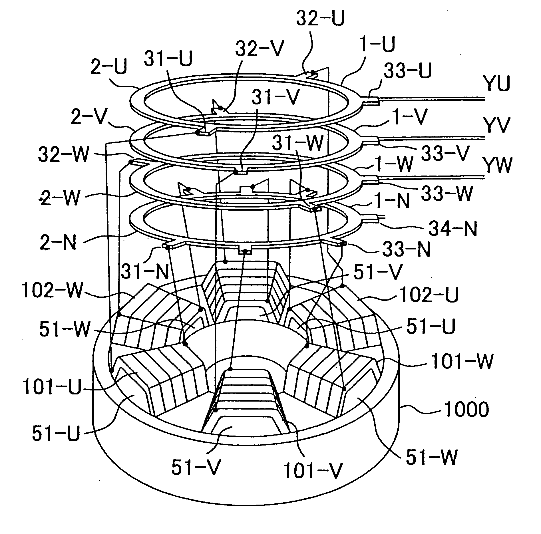
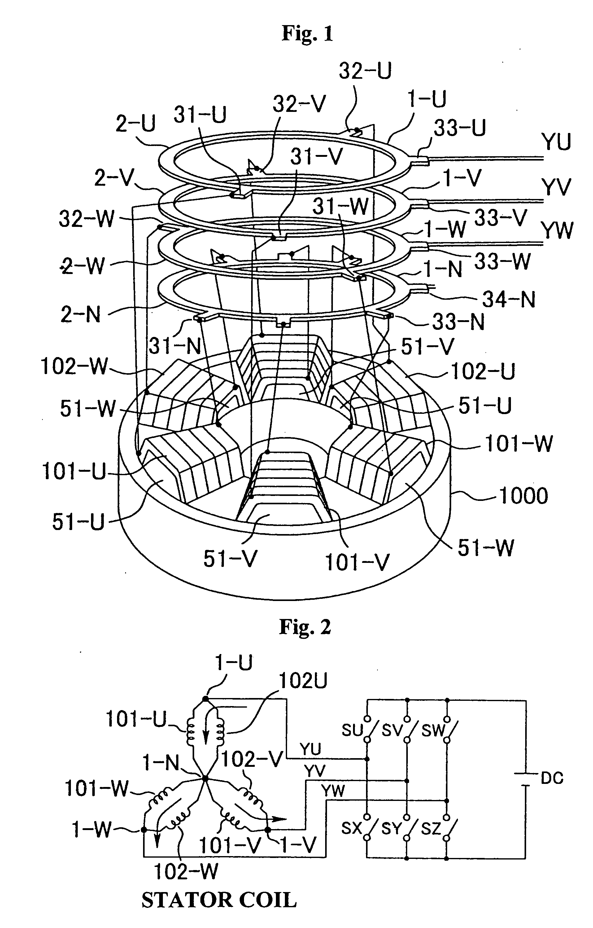
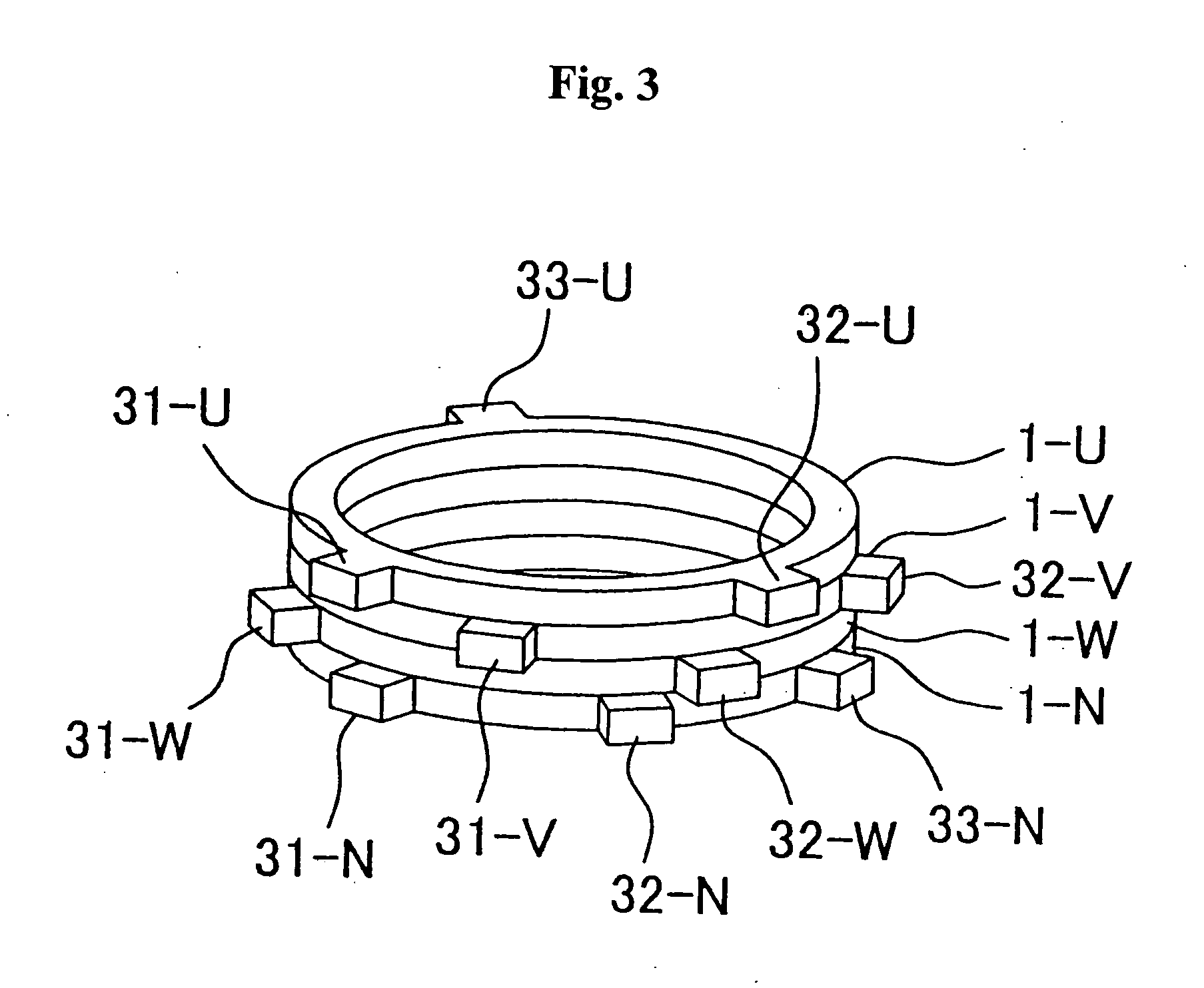
[0069] Referring to FIG. 8, a motor according to the invention will be described. The ring conductors 2-U, 2-V, 2-W, and 2-N are manufactured with different diameters, for example, with the ring diameter decreased in order of, e.g., U-phase, V-phase, W-phase, and N-phase, to which projecting terminals 31-U, 31-V, 31-W, 31-N and so on are mounted to the peripheries thereof; thus, the phase bus bars 1-U, 1-V, 1-W, and 1-N are completed. The bus bars 1-U, 1-V, 1-W, and 1-N are then concentrically assembled in one plane of the ring conductors. The extracting ends of the coils are extracted in correspondence with the terminal positions of the bus bars, which are connected together as shown in FIGS. 1 and 2 of the description of the background art. With the connection, the electrical connection is exactly the same as that of the background art, so that the motor can maintain the same performance as that of the background art.

[0070] The use of the bus bars of this embodiment eliminates the...

second embodiment

[0112] the brushless DC motor will then be described. Too small slot opening width S decreases the torque constant of the brushless DC motor in relation to leakage flux to reduce the output and rapidly increases the ripple of the counter electromotive voltage to lower the operability of the steering. Thus, lower limit of slot opening width S must be determined. FIG. 19 shows a graph of the change in torque constant (expressed as Kt in FIG. 19) of the brushless DC motor and the ripple of the counter electromotive voltage generated in the coils (expressed as emf ripple in FIG. 19) by computer simulation when the slot opening width S in certain shape is varied from zero to the space length G. When the slot opening width S is decreased, i.e. the space between the teeth 11 is decreased, an inflection point at which the torque constant rapidly decreases, or the content of the ripple rapidly increases appears near the point at which the opening width S is 20 percent of the space length G. ...


PUM


Abstract

A motor comprising a motor-wiring bus bar including a plurality of annular ring conductors connecting lead wires of the motor including a stator in which a plurality of stator cores having the lead wires is arranged in a circle or connecting the lead wires and a power line together and a plurality of terminals attached to the ring conductors. The ring conductors are different in diameter and arranged concentrically on a same plane.

Description

FIELD OF THE INVENTION [0001] The present invention relates to a motor, a method for manufacturing the motor, and a motor drive controller. More particularly, the invention relates to a motor including a motor-wiring bus bar used for electrically connecting a lead wire wound around a stator core and its manufacturing method, relates to a permanent-magnet motor which requires low cogging torque, low torque ripple, and high output with compact size and which includes a rectangular-wave driven distributed-coil stator, relates to a brushless DC motor used in an electrically driven power steering system having no motor lock and in which size reduction, low torque ripple, and low cost are achieved, and relates to a brushless-motor drive controller in which the toque ripple is reduced with high rpm in a low-torque load range. BACKGROUND [0002] Bus bars have been used to connect lead wires (hereinafter, referred to as coils) wound around motor stator cores in view of assemble efficiency. Fo...

Claims


Application Information

Patent Timeline
IPC IPC(8): B62D5/04H02K3/52H02P6/10
CPCB62D5/0403H02K3/522H02P2209/07H02P6/10H02K2203/09
Inventor NAKAYAMA, SACHIOWADA, MASARUWATANABE, YOSHIYUKI
Owner NSK LTD
Why Eureka
Try Eureka