Wire grid polarizer

a wire grid and polarizer technology, applied in the direction of polarising elements, instruments, optics, etc., can solve the problems of large complex structure of image display apparatus, large power consumption, and inability to change the shape of glass substrate on which the wire grid is formed, etc., to achieve efficient use and low power consumption

Inactive Publication Date: 2005-09-01
VICTOR CO OF JAPAN LTD
View PDF10 Cites 42 Cited by
  • Summary
  • Abstract
  • Description
  • Claims
  • Application Information

AI Technical Summary

Benefits of technology

[0019] That is to say, the present invention provides a wire grid polarizer that when used in an image display apparatus, even when the image display apparatus is of a small compact structure and provides high output of power from the light source, enables shape transformation of the...

Problems solved by technology

The following problems arise when a wire grid polarizer as described above is used for a high output image display apparatus having substantial light output from the light source.
There is concern that the form of the glass substrate on which the wire grid is formed may be changed as a result of such heat.
If the shape of the glass substrate of a wire grid polarizer in an image display apparatus is altered the quality of images displayed deteriorates considerably as distortion and positional shift in the displayed image occurs.
In order to prevent such shape transformation due to heating of the glass substrate a cooling mechanism is required making the structure of such an image display apparatus large and complex.
Further, t...

Method used


Image

  • Wire grid polarizer
  • Wire grid polarizer
  • Wire grid polarizer

Examples


Embodiment Construction

[0023] The embodiments of the image display apparatus according to the present invention will now be described in detail with reference to the drawings.

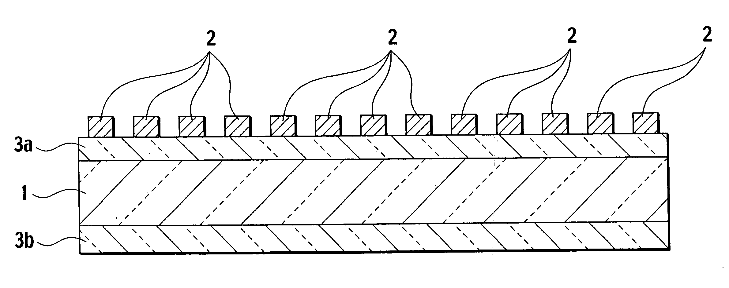
[0024]FIG. 1 provides a cross-sectional view showing the structure of a wire grid polarizer according to the present invention.

[0025] As shown in FIG. 1, this wire grid polarizer consists of elements wherein a comb shaped wire grid 2 of a metal such as aluminum or tungsten or the like is formed on a glass substrate 1.

[0026] This wire grid polarizer performs polarized light separation in respect of light incident to the surface on that side on which the wire grid 2 is formed. That is to say, this wire grid polarizer reflects polarization elements parallel to the comb shaped wire and passes elements orthogonal thereto. These properties of this wire grid can be used for a variety of purposes for polarization separation such as frequency separation using polarization or as a side band removal filter.

[0027] The wires of the wire grid ...


PUM


Abstract

To provide a wire grid polarizer used in an image display apparatus, in which even when the image display apparatus is of a small compact structure and provides high output of power from the light source, shape transformation of the glass substrate occurring due to generation of heat caused by light absorption in the wire grid is prevented and in which by efficient usage of light rays from the light source, high-quality images can be displayed by the image display device and power consumption is low. A wire grid 2 formed of metal in a fine comb shape is formed on a glass substrate 1 and antireflection coatings 3a and 3b are disposed respectively on the front surface part and the rear surface part of the wire grid 2 of the glass substrate 1.

Description

FIELD OF THE INVENTION [0001] The present invention relates to a wire grid polarizer used as polarized light separating elements for a liquid crystal projector apparatus or the like. BACKGROUND OF THE INVENTION [0002] Projection type image display apparatuses using reflective type liquid crystal spatial light modulating elements have been proposed in conventional technology. Such image display apparatuses comprise a light source, an optical system in which spatial light modulating elements are illuminated by light rays emitted from the light source and a light projection system that projects modulated light modulated by the spatial light modulating elements onto a screen. [0003] Reflective type liquid crystal spatial light modulating elements are elements that reflect projected light rays, modulating the condition of polarization thereof for each pixel, in response to an externally supplied image signal. [0004] In such a conventional image display apparatus, modulated light modulate...

Claims


Application Information

Patent Timeline
IPC IPC(8): G02B5/30G02F1/13
CPCG02B5/3058
Inventor FUKUZAKI, YOSHIO
Owner VICTOR CO OF JAPAN LTD
Why Eureka
Try Eureka