Arrangement for mixing of fluid streams

a technology for mixing fluid streams and fluid streams, applied in the direction of traffic signals, transportation and packaging, roads, etc., can solve the problems of increasing the distance in a duct to achieve the same degree of mixing, reducing the degree of mixing or mixing efficiency, and reducing the pressure loss.

Active Publication Date: 2005-09-01
HALDOR TOPSOE AS
View PDF7 Cites 13 Cited by
  • Summary
  • Abstract
  • Description
  • Claims
  • Application Information

AI Technical Summary

Benefits of technology

[0039] In another advantageous embodiment of the invention, one protrusion extends only slightly away from the main body and corresponds to a region located near and substantially below the outlet of the at least one second fluid stream. Hence, the injection means, for example a conduit for the introduction of ammonia into the major stream, is adapted so as to provide for the impact or contact of the at least one second stream onto at least a partial region of the back side of the solid plate. In this manner back-flow of the second stream is prevented: it is prevented that the second stream travels downward below the solid plate (mixing device) and into its front section. Instead, the second stream is directed upward into the turbulent flow being created downstream, i.e. on the back side of the solid plate.
[0040] As a result of the invention the degree of mixing or mixing efficiency is improved within a given mixing distance or within a given (commercially acceptable)

Problems solved by technology

The use of static mixers has the penalty that their use manifests itself in considerable pressure loss in the duct, with the attendant effect of costly energy losses.
Because the outlet opening of the second stream being injected into the duct carrying the first major stream may only protrude a short distance inwardly from the wall of the duct, the concentration of the active species of the second stream, e.g. ammonia, towards the centre of the duct may tend to decrease, thus contributing to poor mixing.
Poor mixing or poor homogeneity of the injected ammonia may imply higher NOx levels in the stack as well as unwanted levels of ammonia passing unreacted through the catalyst unit.
These describe relatively expensive hollow mixing devices with protrusions or projections directed inward from the periphery of the devices.
However, they are rather expensive and may require a greater number of injection points for the introduction of a second stream into the major fluid stream than when utilising regular shaped static mixing devices.
This configuration promotes the creation of turbulent flow re

Method used


Image

  • Arrangement for mixing of fluid streams
  • Arrangement for mixing of fluid streams
  • Arrangement for mixing of fluid streams

Examples


Embodiment Construction

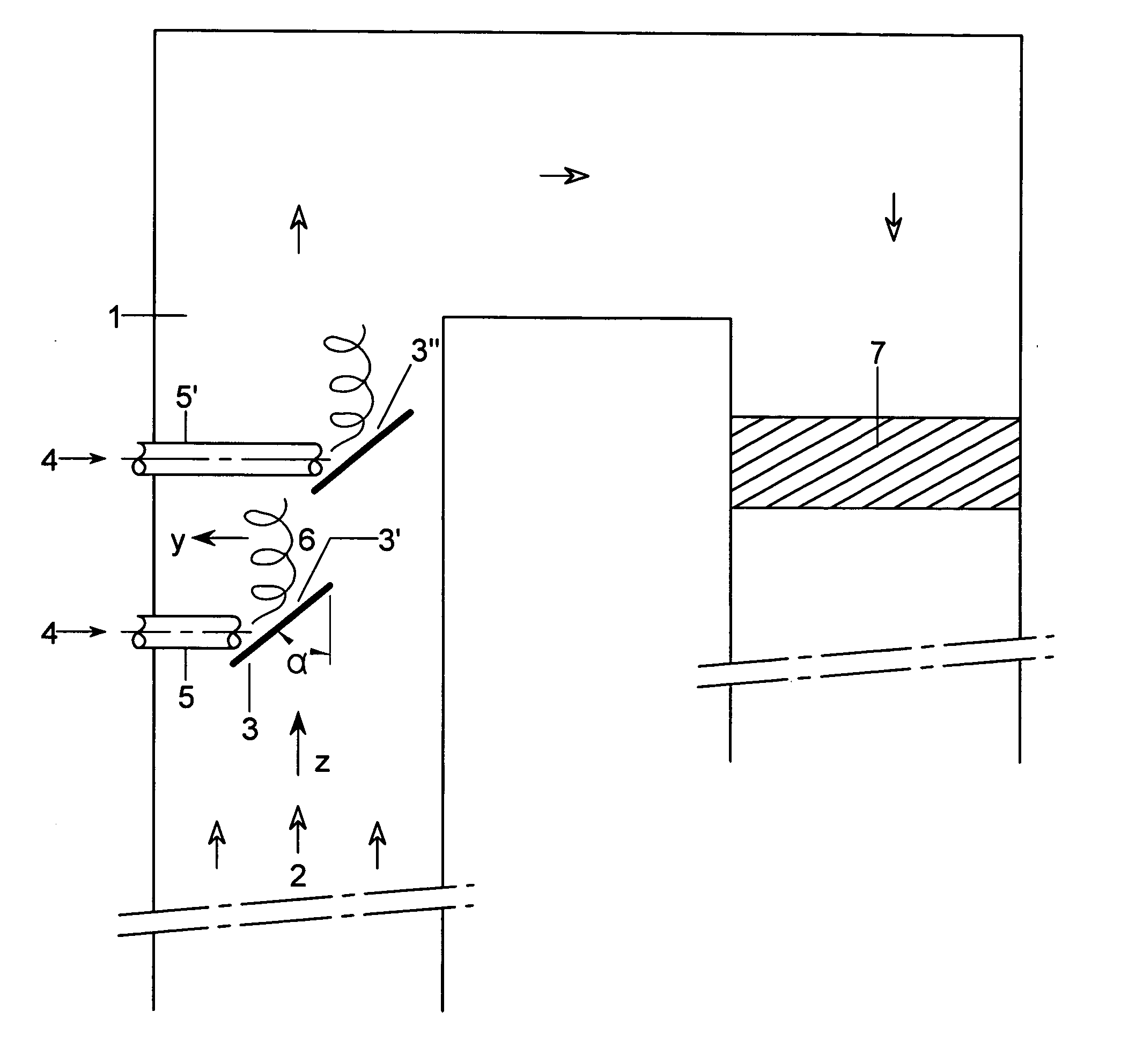
[0045] The invention is illustrated in the accompanying drawings, wherein FIG. 1 shows a schematic vertical cross-sectional view of a flue gas section according to the invention.

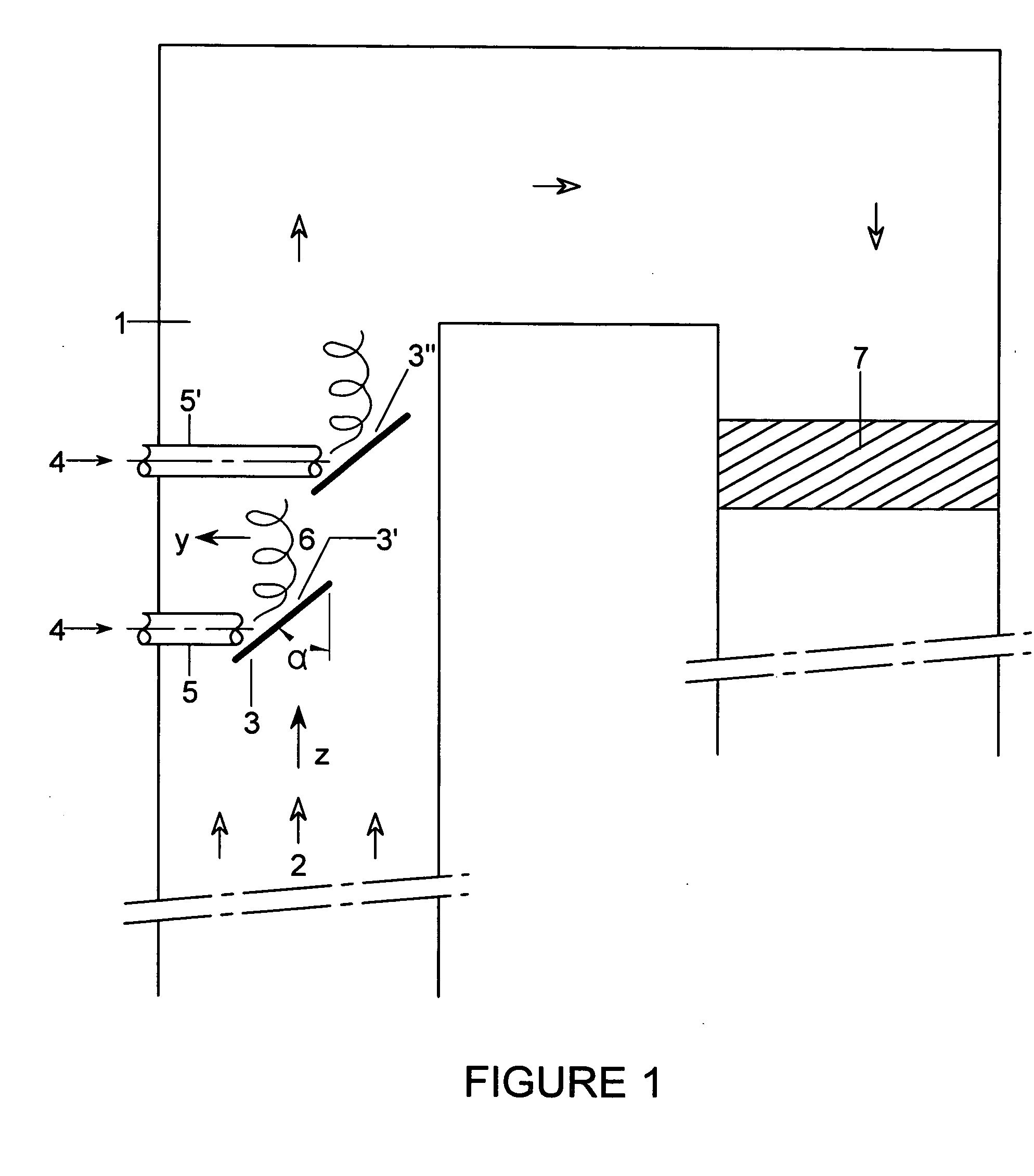
[0046]FIG. 2 shows a cross-sectional view of a mixer according to the invention positioned within a square duct.

[0047]FIG. 3 shows a graph describing degree of mixing as a function of pressure loss for a mixing device according to the invention with respect to a conventional circular mixing device.

[0048] In FIG. 1 the flue gas section for reduction of nitrogen oxides comprises a duct 1 having rectangular section through which a flue gas 2 passes. The flue gas represents a first major fluid stream travelling in direction Z and collides with the front side of mixing device 3, which is disposed substantially transversally to the travelling direction of said first major fluid stream. Mixer 3 is positioned at incidence angle α with respect to the travelling direction of the major fluid stream 2. A second fluid ...


PUM

PropertyMeasurementUnit
Timeaaaaaaaaaa
Angleaaaaaaaaaa
Angleaaaaaaaaaa

Abstract

An arrangement for mixing fluid streams in a duct, said arrangement comprising: at least one mixing device having front side and back side and positioned within said duct through which a first major stream travels, the at least one mixing device determining a total cross-sectional area which is significantly lower than that of the duct so as to allow for the passage of said first major stream, in which the at least one mixing device is a solid plate provided with one or more protrusions extending outward from the main solid plate body.

Description

FIELD OF THE INVENTION [0001] The present invention relates to an arrangement for the mixing of fluid streams in a duct with at least one mixing device being positioned within said duct and in particular the invention relates to a novel mixing device for such an arrangement. [0002] The invention relates particularly to arrangements of this type, which are constructed so as to be suitable for use in applications including reduction of nitrogen oxides and reduction of sulphuric acid from acid mist in flue gas cleaning. BACKGROUND OF THE INVENTION [0003] The proper mixing of single fluid streams or several fluid streams that interact in ducts or channels requires the presence of relatively turbulent regions by the generation of velocity components transverse to the main major fluid stream passing through the duct. In order to achieve proper mixing between for instance one or more fluid streams being injected into a major fluid stream, a certain distance along the duct (channel) is requ...

Claims


Application Information

Patent Timeline
IPC IPC(8): B01F23/10B01F23/30
CPCB01F23/10B01F23/20B01F25/3131B01F25/43163B01F25/4316B01F35/55E01F9/541
Inventor HANSEN, MICHAEL
Owner HALDOR TOPSOE AS
Why Eureka
Try Eureka