Single use applicator for applying viscous fluids

a technology of fluid application and applicator, which is applied in the direction of carpet cleaners, brushes, hand devices, etc., can solve the problems of reducing the efficiency of the device, limiting the amount of fluid to be dispensed, and the applicator to drip fluid from the tip first and then slow down, so as to achieve fast and easy technique of “wet out” the application tip and uniform fluid flow

Inactive Publication Date: 2005-09-01
FRAZIER THOMAS G
View PDF12 Cites 58 Cited by
  • Summary
  • Abstract
  • Description
  • Claims
  • Application Information

AI Technical Summary

Benefits of technology

[0019] A further object of the invention is to provide a single use applicator that provides a fast and easy technique to “wet out” its application tip.
[0020] A further object of the invention is to provide a single use applicator that can be used in the vertical downward, horizontal and inverted upward positions, and which provides a uniform fluid flow to the tip in all positions.
[0021] A further object of the invention is to provide a single use applicator that provides for the optimal applicational use of expensive and environmentally dangerous fluids, by limiting the VOC's to the minimum, while providing use up rates up to 90% of the fluid stored in the applicator ampoule A further object of the invention is to provide a single use applicator that includes an airtight cap to allow multiple uses of the fluid contained in the applicator ampoule, within an extended time frame allowed from initial applicator activation time.
[0022] A further object of the invention is to provide a single use applicator that can dispense and apply a band of viscous fluid onto a variety of application surfaces.

Problems solved by technology

This design technique, however, allows a significant quantity of the dispersed fluid to remain in the tip after use, thereby reducing the efficiency of the device and also limiting the amount of fluid to be dispensed.
Additionally, when these prior art applicator devices with an application tip saturated with the application fluid are held in the downward position, the unabsorbed fluid above the saturated porous application tip creates hydrostatic head pressure, which is directly proportional to the fluid height above the tip, and will cause the applicator to drip fluid from the tip at first and then slow down as the hydrostatic head is reduced, thereby creating a non uniform fluid application.
Non-uniform fluid application is particularly abhorrent when applying adhesion promotion primers to metal, glass or other hard surfaces.
In addition, the '962 device requires the use of a pre-filter, making the device costly to assemble.
Too great a squeeze pressure will cause the applicator brush to drip, or cause too much, or varying amounts of fluid to be applied to the surface.
Using the Andrews device in an inverted upward position to apply a uniform application, is particularly difficult, if not impossible, as a constantly increasing finger tip pressure would be required to apply a uniform band of the application fluid.
Depending on how the device was stored prior to activating (i.e. tip up or tip down), non uniform results are obtained as the tip is very likely to drip if stored with tip down, and if stored with the tip up prior to activating, the fibrous tip is likely to be dry of most fluid, and the user would be back to the long time frame required for the tip to “wet out”.
Since the body housing the '522 device is not deformable (because it is glass) reducing the “wet out” time of the brush tip by squeezing the body housing is not possible.
Finally this device exposes the ampoule to accidental breakage prior to use since it is housed in an unprotected glass body.
This condition, at the beginning of use, would cause excessive flow to the tip (and perhaps cause dripping).
However, when used in an inverted upward position, the flow rates would fall off dramatically since the porous plug would be starved for a continued flow of fluid as the '488 structure makes no provision for an internal and adjacent reservoir section (with lower porous density) as part of the porous plug.
Moreover, the user would have to squeeze the applicator to increase flow, and excessive fluid laydown could result.
If used in the tip down configuration, there is no way to slow down the fluid flow once the uniform density of the tip is chosen for the design.
If the density of the tip is chosen so as to allow a certain flow rate while there is a hydrostatic head pressure over the tip (i.e. at the start of use of the device), the flow will necessarily be inadequate when this hydrostatic head is reduced or absent.
To increase the flow in the '488 device would require the unreliable technique of squeezing the tube to restore fluid flow.
Wirt in U.S. Pat. No. 5,288,159 does not allow use of ‘non-ideal’ fluids (i.e. fluids with viscosities greater than water) since there is no way to speed up “wet out” times. The '159 device has an air vent in the top, so that squeezing the tube to increase the internal pressure above the fluid, even if possible, would not force the viscous fluid through the applicator pad.
Additionally, since there is not internal fibrous reservoir next to the applicator pad, to “feed” fluid via capillary action, the device cannot be used effectively for inverted and upward operational positions.
Fluid is dispersed in all directions making the device inefficient, as a large portion of the application fluid will remain in the device as absorbed fluid, and undeliverable to the open end of the applicator.
In the case of very expensive viscous fluids, to overcome this characteristic of the '245 device would require filling the ampoule with excessive fluid, causing the device's cost to be uneconomical.

Method used


Image

  • Single use applicator for applying viscous fluids
  • Single use applicator for applying viscous fluids
  • Single use applicator for applying viscous fluids

Examples


Embodiment Construction

[0041] When referring to the preferred embodiments, certain terminology will be utilized for the sake of clarity. Use of such terminology is intended to encompass not only the described embodiments, but also technical equivalents, which operate and function in substantially the same way to bring about the same result.

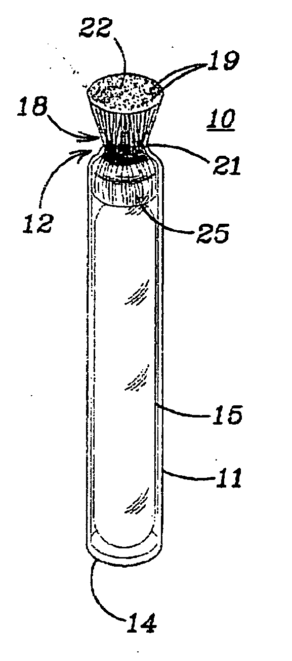
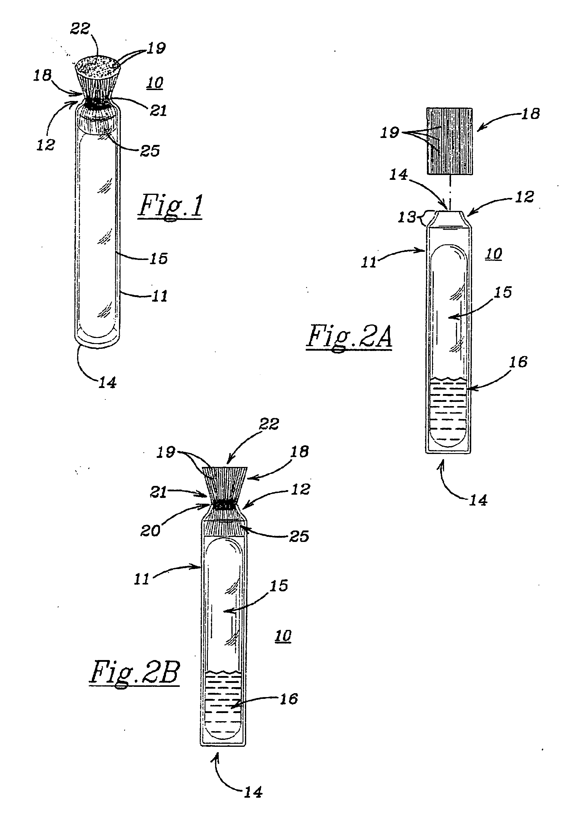
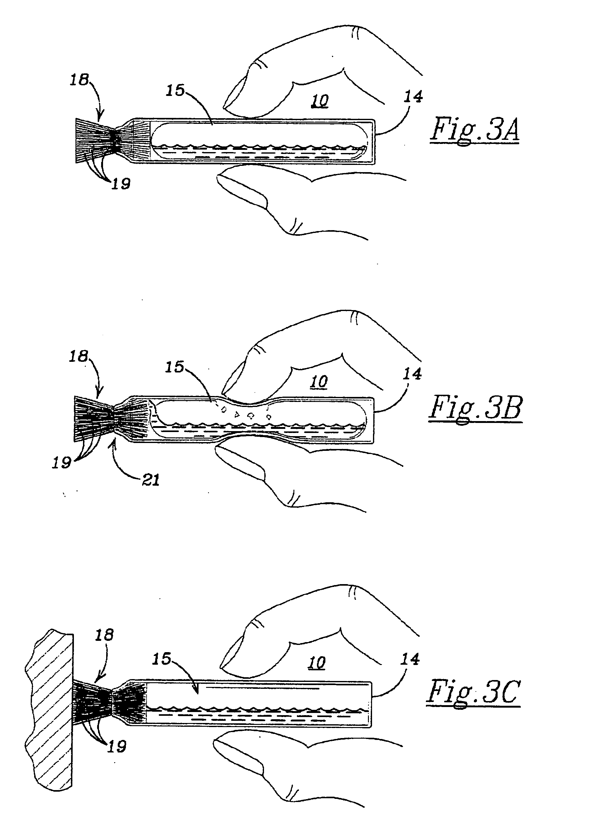
[0042] Referring now to more particularly to the drawings and FIG. 1-6B thereof an embodiment of the single use applicator device 10 is therein illustrated.

[0043] The device 10 includes an outer cylindrical tube body 11, which is open at one end 12, with a rim tapering section 13, and which is closed at its other end 14.

[0044] The tube 11 is preferably constructed of a chemically inert thermoplastic resin of well known type such as polyethylene resin. The body 11 is capable of being readily deformed by finger pressure of the user, and returns to its original shape upon pressure release. The resin material comprising the tube 11 is also capable of being compressed and...


PUM


Abstract

A single use applicator for dispensing and applying a thin layer of viscous fluid, comprising an outer body of chemically inert deformable material open at one end, a crushable glass ampoule therein containing fluid to be dispensed and applied, and an application element of synthetic fiber strands in said tube, wherein fluids flows by capillary action, with an internal reservoir inside the tube adjacent the ampoule, a fluid control valve welded to the tube at its approximate mid point, to control fluid flow, and an external tip to apply the fluid to an application surface.

Description

BACKGROUND OF THE INVENTION [0001] 1. Field of the Invention [0002] This invention relates to a single use applicator for applying viscous fluids having viscosities greater than water, and is of the type which includes fluid carried in a hermetically sealed crushable glass ampoule, with an anhydrous inert gas head, which ampoule is contained in a chemically inert deformable tube, with an application element comprised of a plurality of synthetic fiber strands bonded thereto. The application element has a centrally located restrictive valve section to control fluid flow, with an internal fluid reservoir section adjacent the ampoule, and an external tip section to apply the fluid. [0003] 2. Description of the Prior Art [0004] Applicators for dispensing fluids for various uses, and which are of the single use type are well known in the art. Such applicators take many forms, but the most common device is one that contains a thin walled glass ampoule that contains fluid, which ampoule is ...

Claims


Application Information

Patent Timeline
Patent Type & Authority Applications(United States)
IPC IPC(8): A46B11/00A46B11/04A47L13/22B43K5/14B43M11/06
CPCA46B11/0003B43M11/06A46B2200/20A46B11/0013
Inventor FRAZIER, THOMAS G.
Owner FRAZIER THOMAS G
Why Eureka
Try Eureka