
Electric machine with thermosiphon-type cooling system

a cooling system and thermosiphon technology, applied in the direction of windings, magnetic circuit rotating parts, magnetic circuit shape/form/construction, etc., can solve the problems of unfavorable bearing heating, unfavorable bearing heating, and generation of unwanted heat by air stream itself, so as to achieve the effect of preventing inadmissible bearing heating

Inactive Publication Date: 2005-09-08
SIEMENS AG
View PDF10 Cites 30 Cited by
  • Summary
  • Abstract
  • Description
  • Claims
  • Application Information

AI Technical Summary

Benefits of technology

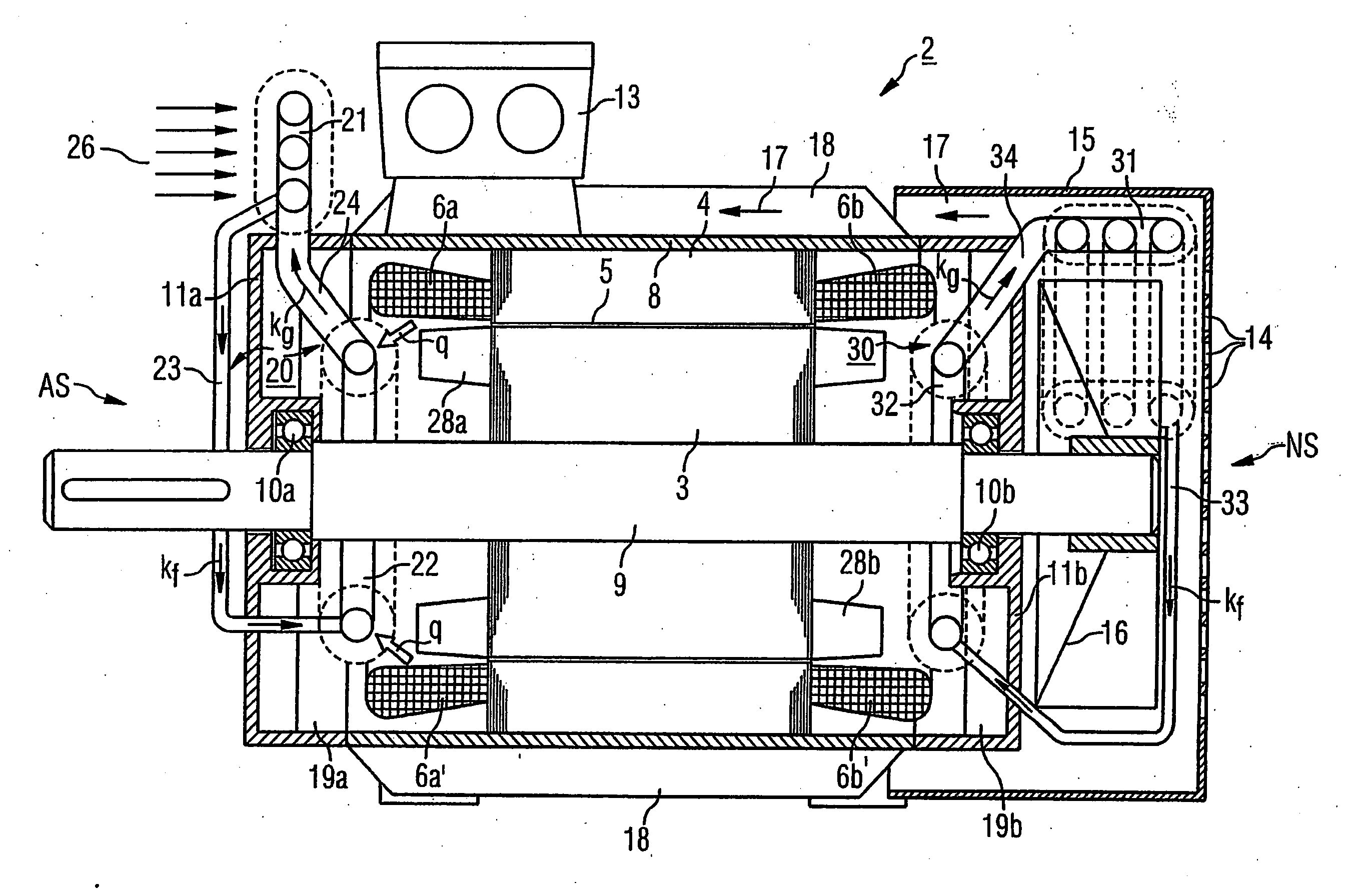
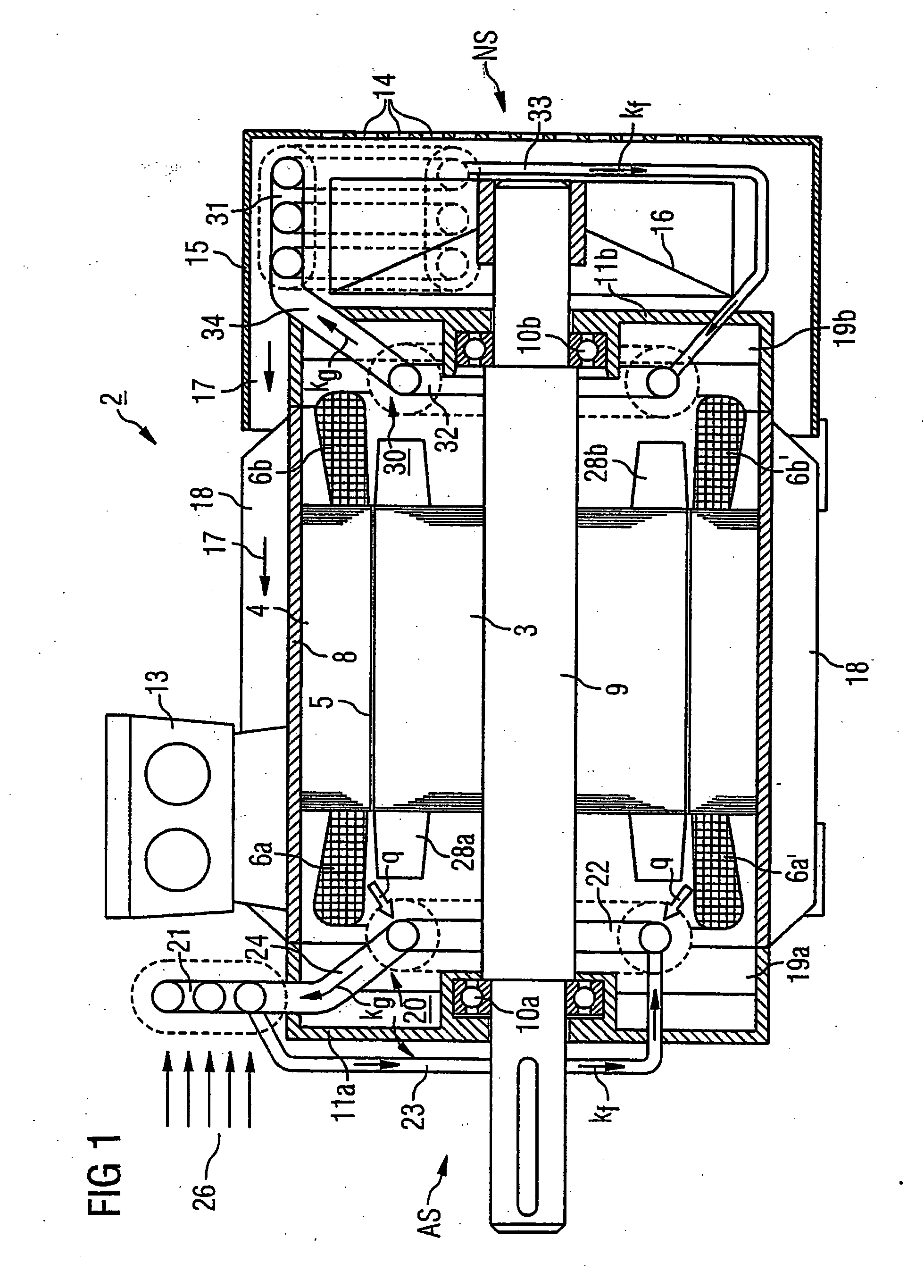
[0014] The provision of a closed-flow system using the natural thermosiphon effect in which the inner heat transport of a coolant ensures a highly efficient heat conduction during phase transitions, loss heat can be removed practically directly from the involved heat source inside the machine housing to the outside, e.g. to cooling air or another heat sink such as, e.g., water, or sea water in the event of a ship's motor. There is no need to overcome relevant thermal heat barriers such as housing walls or air gaps. In addition, thermal stress on other machine components such as, e.g., bearings, is decreased. The thermosiphon effect of the cooling device is implemented in the absence of any moving parts and thus can be constructed maintenance-free and self-regulating.
[0015] Compared to purely air-cooled machines, the direct heat removal at the source of the heat losses by establishing natural thermosiphon allows a reduction in the air volume flow. As a consequence, the air stream generates less heat, further contributing to a reduction of the air volume. Compared to a conventional electric machine of same power output, an electric machine according to the present invention operates more efficient and is cost-saving as far as production is concerned, in particular as it related to the winding and the laminated stator core. Moreover, the reduction of the air volume flow also lessens noise development.
[0016] According to another feature of the present invention, the housing has opposite end surfaces, wherein the closed-flow system may be disposed at one of the axial ends, whereas a second such closed-flow system is disposed at the other one of the axial ends of the electric machine. In this way, the evaporators of both closed-flow systems are able to effect a substantially even cooling action especially in the area of the end windings of the stator winding parts and / or shaft bearings.
[0019] According to another feature of the present invention, the evaporator may be constructed in heat-conducting connection with at least one of the end windings. Thus, heat generated by the end winding can be directly removed by the thermosiphon effect in the closed-flow system without inadmissible heating of other machine components, such as the associated bearing.
[0020] According to another feature of the present invention, the housing may have opposite end plates, with the evaporator being constructed for heat-conducting connection with at least one of the end plates. Suitably, the evaporator may be integrated in the one end plate. As the end plate is normally in heat-conducting connection with a bearing, inadmissible heating of the bearing can thus easily be prevented.

Problems solved by technology

This approach not only requires complicated sealing measures but also demands considerable safety measures.
A shortcoming associated with this approach is generation of unwanted heat by the air stream itself as a result of friction losses.
This approach leads, however, to an uneven temperature profile in the motor, as has been described in the magazine “Drive and Control, number 1, 1992, pages 10 to 12.
While the bearing and end winding of the stator winding on the non-driving side of the electric machine are normally subjected to temperatures below their thermal limits, the driving side, on the other hand, encounters higher temperatures which subject the bearing and end winding of the stator winding on this driving side to greater stress, ultimately causing harm to the electric machine.
While heat may be transferred from the laminated stator core to the immediately adjacent surrounding outer housing, this approach is insufficient to remove enough heat from the area of the end windings which project out from the stator core at the ends thereof.
The air gap represents, however, a significant heat barrier.
As a result, the service life of the bearing is adversely affected because the average bearing temperature and temperature differential between the typical ring-shaped bearing inner and outer parts is too high.
This requires however measures to prevent the end surfaces of the housing from being exposed to excessive heat because the shaft bearings at these zones cannot be subjected to temperatures beyond a set maximum value.

Method used


Image

  • Electric machine with thermosiphon-type cooling system
  • Electric machine with thermosiphon-type cooling system
  • Electric machine with thermosiphon-type cooling system

Examples


first embodiment

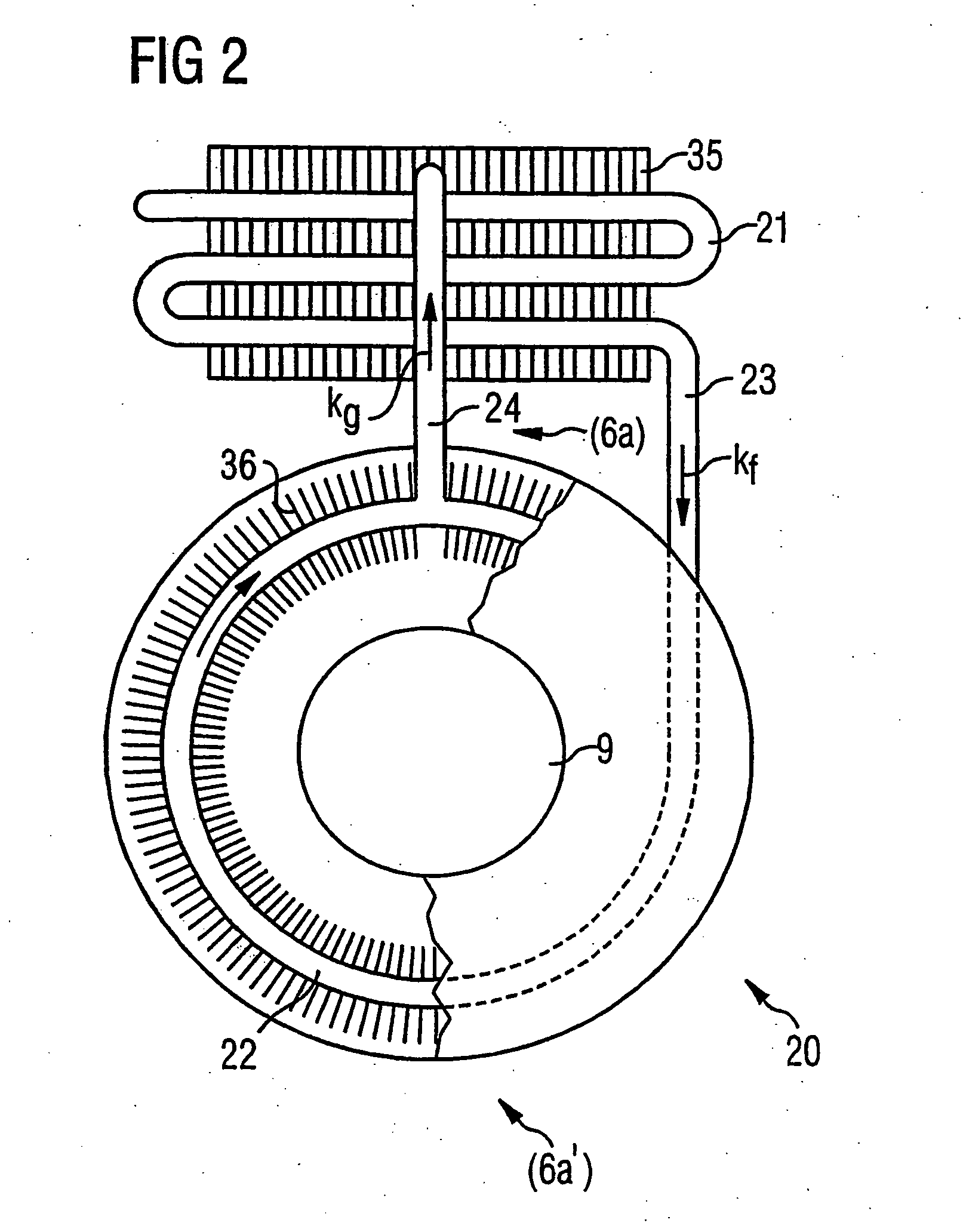
[0032] Turning now to the drawing, and in particular to FIG. 1, there is shown a sectional view of an electric machine according to the present invention; generally designated by reference numeral 2 and having a rotor core 3 formed of a plurality of stacked laminations, and a stator core 4 formed of a plurality of stacked laminations in distanced surrounding relationship to the rotor core 3 to define a narrow air gap 5 therebetween. The stator core 4 includes a stator winding which terminates in two end windings 6a, 6a′ and 6b, 6b′ at the axial ends of the stator core 4. In the non-limiting example of FIG. 1, each side includes a single-part or multi-part end winding whose lower portion is situated at a colder environment and is distinguished here by a prime. Immediately adjacent to the stator core 4 in surrounding relationship thereto is a motor housing 8 which is traversed by a rotor shaft 9 having opposite axial ends supported by respective bearings 10a, 10b. The housing 8 is clo...

third embodiment

[0041] Turning now to FIG. 4, there is shown a sectional view of an electric machine according to the present invention, generally designated by reference numeral 39. Parts corresponding with those in FIG. 3 are denoted by identical reference numerals and not explained again. The description below will center on the differences between the embodiments In this embodiment, provision is made for a common thermosiphon-type closed-flow system, generally designated by reference numeral 40. The thermosiphon 40 includes a single condenser 43, disposed anteriorly of the fan wheel 16, and two evaporators 22A, 32A respectively arranged at the axial ends of the electric machine 39 for absorbing heat generated by the end windings 6a, 6a′ and 6b, 6b′. The evaporators 22A, 32A are interconnected by a lower collecting conduit 41 for conducting condensed coolant kf, and an upper collecting conduit 42 for conducting evaporated coolant kg. In other words, the collecting conduit 42 is disposed at a geo...

fourth embodiment

[0044] Turning now to FIG. 5, there is shown a sectional view of an electric machine according to the present invention, generally designated by reference numeral 44. Parts corresponding with those in FIG. 4 are denoted by identical reference numerals and not explained again. The description below will center on the differences between the embodiments. The electric machine 44 has a thermosiphon-type closed-flow system 45 with collecting conduit 41 for liquid coolant kf and collecting conduit 41 for gaseous coolant kg. The collecting conduits 41, 42 are connected to evaporators 22B, 32B which are respectively disposed on the radial outer sides of the end windings 6a, 6a′ and 6b, 6b′ in heat-conducting connection therewith. The thermosiphon 45 includes a condenser 46 on the end surface of the housing 8 at the non-driving side NS of the electric machine 44. For example, the condenser 46 may be directly mounted to or integrated in the end plate 11b. To improve the heat exchange, the con...


PUM


Abstract

An electric machine includes a housing for accommodating a rotatably supported rotor and a stationary stator, and a cooling device for cooling heat-generating components of the rotor and the stator. The cooling device comprises a closed-flow system having an evaporator disposed in the housing, a condenser disposed outside the housing at a geodetically higher location, and a closed tube assembly, which connects the condenser and the evaporator, for circulating a coolant using a thermosiphon effect as a result of a difference in density between vapor and liquid portions of the coolant. The closed-flow system contains a liquid-vapor mixture of the coolant in a saturated state and includes a first tube for conducting coolant to the evaporator and a second tube for conducting coolant away from the evaporator. The first tube has hereby a cross section which is smaller than a cross section of the second tube.

Description

CROSS-REFERENCES TO RELATED APPLICATIONS [0001] This application is a continuation of prior filed copending PCT International application no. PCT / DE2003 / 003014, filed Sep. 11, 2003, which designated the United States and on which priority is claimed under 35 U.S.C. §120 and which claims the priority of German Patent Application, Serial No. 102 44 428.5, filed Sep. 24, 2002, pursuant to 35 U.S.C. 119(a)-(d).BACKGROUND OF THE INVENTION [0002] The present invention relates, in general, to the field of electric machines. [0003] Nothing in the following discussion of the state of the art is to be construed as an admission of prior art. [0004] German patent publication no. DE 42 42 132 A1 describes an electric machine having a housing for accommodation of a rotor, which is constructed in the form of a laminated rotor core and includes a rotor shaft, and a stator. Placed inside the housing is a fan, which is arranged on both ends of the rotor shaft. Cooling channels extend in the rotor cor...

Claims


Application Information

Patent Timeline
IPC IPC(8): H02K9/00H02K9/18H02K9/20
CPCH02K9/20H02K9/14H02K9/225
Inventor GROMOLL, BERNDHANDWERKER, MICHAELKRIEG, OLAF
Owner SIEMENS AG
Learn More