Differential amplifier with large input common mode signal range

Inactive Publication Date: 2005-09-08
AVAGO TECH INT SALES PTE LTD
View PDF9 Cites 13 Cited by
  • Summary
  • Abstract
  • Description
  • Claims
  • Application Information

AI Technical Summary

Benefits of technology

[0055] Advantageously, the differential amplifier optimizes its input common mode signal range using differential pairs of the same type. This mitigates difficulties faced in fabricating differential pairs with matching gains and similar transient behaviors.
[0056] Furthermore, the differential amplifier does not require a subsequent stage to provide loads for its amplifying MOSFETs or to process additional output signals. Thus, it consumes both less po

Problems solved by technology

Unfortunately, while the use of active devices for current sources and loads has several advantages, it also presents the problem of limiting the input common mode signal range.
This common mode confinement is particularly difficult in applications seeking to meet, for example, IEEE Std 159

Method used


Image

  • Differential amplifier with large input common mode signal range
  • Differential amplifier with large input common mode signal range
  • Differential amplifier with large input common mode signal range

Examples


Embodiment Construction

[0072] The present invention relates to a method of extending an input signal range of a component that receives the input signal. Specifically, the present invention relates to a design for an amplifier that extends its input signal range. More specifically, the present invention relates to a design for a differential amplifier with a large input common mode signal range.

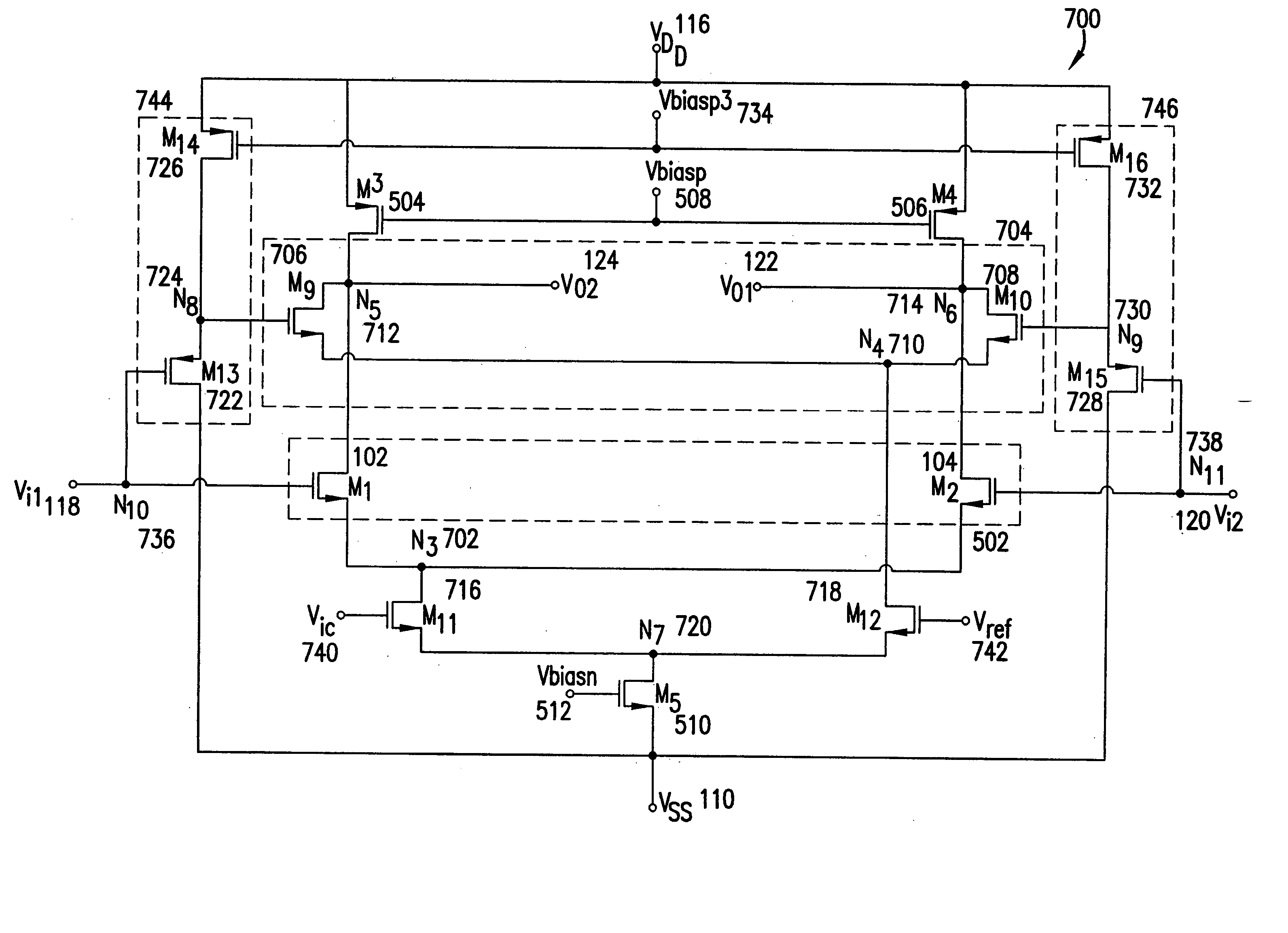
[0073]FIG. 7 is a schematic diagram of a differential amplifier 700 configured to be a NMOSFET embodiment of the present invention. Differential amplifier 700 comprises first differential pair 502 of amplifying NMOSFETs M1 102 and M2 104 with source terminals connected at a first node “N3”702, and a second differential pair 704 of amplifying NMOSFETs “M9”706 and “M10”708 with source terminals connected at a second node “N4”710. First and second differential pairs 502, 704 are connected in parallel. The drain terminals of M1 102 and M9 706 are connected at a third node “N5”712; the drain terminals of M2 104 and M10...


PUM


Abstract

A design for a differential amplifier with a large input common mode signal range. The differential amplifier comprises two differential pairs, each having two amplifying MOSFETs. A source follower is connected to the gate terminal of each amplifying MOSFET in one of the differential pairs. A differential signal applied to the differential amplifier comprises two separate signal. Each separate signal is applied to the gate terminals of both the amplifying MOSFET in the differential pair not driven by the source follower and the driven MOSFET of the source follower. The differential amplifier further comprises a pair of switch MOSFETs connected to a current source MOSFET. The switch MOSFETs act to control the distribution of the total current flowing from the current source MOSFET and, consequently, to determine which differential pair works dominantly to amplify the input signals. Each source follower acts to offset the voltage of its input signal to compensate for the range loss due to the bias voltages and the threshold voltages within the differential amplifier.

Description

[0001] This application is a continuation of U.S. application Ser. No. 10 / 015,887, filed Dec. 17, 2001, which is incorporated herein in its entirety by reference and which claims the benefit of U.S. Provisional Application No. 60 / 256,126, filed Dec. 15, 2000.BACKGROUND OF THE INVENTION [0002] 1. Field of the Invention [0003] The present invention relates to a method of extending an input signal range of a component that receives the input signal. Specifically, the present invention relates to a design for an amplifier that extends its input signal range. More specifically, the present invention relates to a design for a differential amplifier with a large input common mode signal range. [0004] 2. Background Art [0005] Operational amplifiers are key elements used in many analog and mixed analog / digital applications. Increasingly, these applications are being realized in smaller, portable packages, which require low power supply voltages. This necessity taxes the ability of operationa...

Claims


Application Information

Patent Timeline
IPC IPC(8): H03F3/45H03F3/72
CPCH03F3/45183H03F3/4521H03F3/45708H03F2203/7203H03F2203/45371H03F2203/45612H03F3/72
Inventor WANG, HONGWEIVENES, ARDIE
Owner AVAGO TECH INT SALES PTE LTD
Why Eureka
Try Eureka