
Method and apparatus for triggering of lightning discharge

a technology of lightning discharge and triggering method, which is applied in the direction of electrostatic charge, nuclear engineering, nuclear targets, etc., can solve the problems of low triggering efficiency of lightning discharge method, low safety, and low safety of triggering method, so as to achieve high safety

Inactive Publication Date: 2005-09-08
JAPAN NUCLEAR CYCLE DEV INST
View PDF5 Cites 2 Cited by
  • Summary
  • Abstract
  • Description
  • Claims
  • Application Information

AI Technical Summary

Benefits of technology

[0005] An object of the present invention is to overcome the above-described problems in the prior art method for triggering of lightning discharge using a rocket or a laser and to provide a novel method for triggering of lightning discharge in which lightning discharge can be triggered more surely and high lightning triggering efficiency can thereby be obtained.

Problems solved by technology

However, the method for triggering of lightning discharge using a rocket requires that the rocket is launched toward the strong electric field region in a thundercloud where lightning discharge possibly occurs; if the rocket does not reach such a region, there is a possibility that lightning discharge is not triggered and hence the lightning triggering efficiency of this method cannot necessarily be high.
Additionally, there is a possibility that the spent rocket and the spent metal wire might come down to the ground.
On the other hand, the method of artificial triggering of lightning discharge using a laser requires the generation of plasma in air located between a laser injection nozzle and the thundercloud, and accordingly there has been a problem such that, in the case of winter thunderstorms, the plasma can hardly be generated because of the absorption of the laser beam by the ice crystals / snow in and below the thundercloud, and the lightning triggering efficiency is thereby degraded.

Method used


Image

  • Method and apparatus for triggering of lightning discharge
  • Method and apparatus for triggering of lightning discharge
  • Method and apparatus for triggering of lightning discharge

Examples


Embodiment Construction

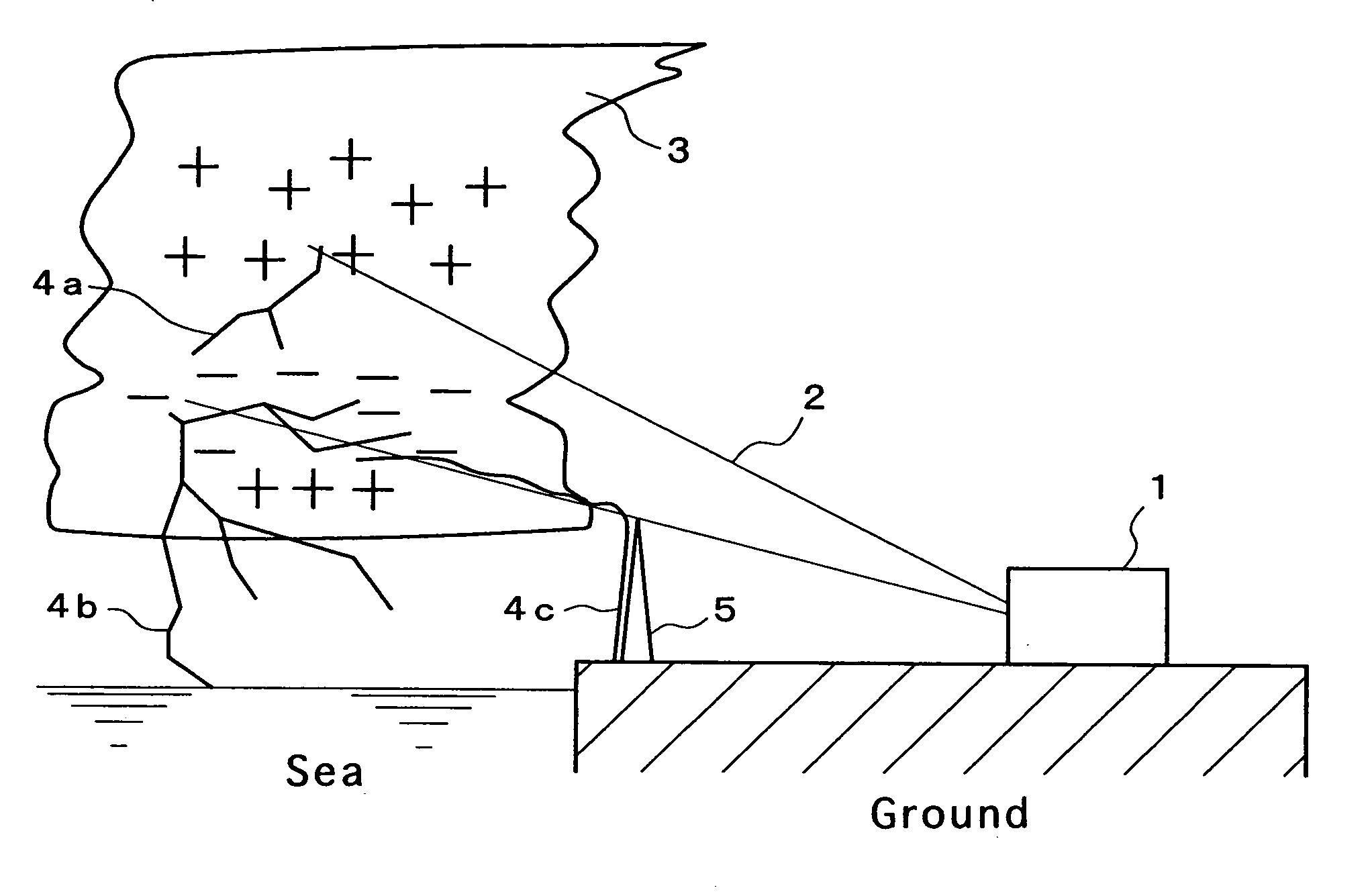
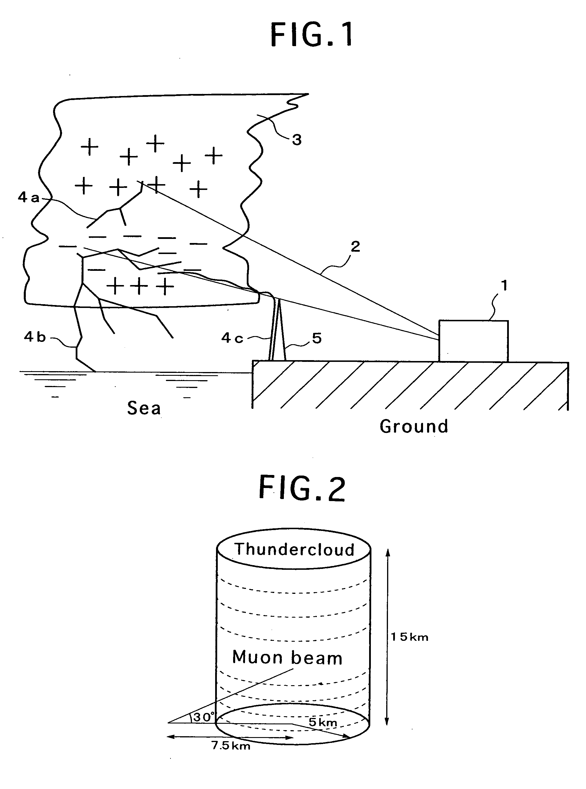
[0021]FIG. 1 is a diagram conceptually illustrating the triggered lightning discharge method of the present invention. The muons produced by a high energy proton or electron accelerator 1 are collimated, and irradiated as a muon beam 2 toward the strong electric field region of a thundercloud 3. When the energy of a muon is 2 GeV, the flying range of the muon is ten-odd kilometers, so that the muons can be irradiated toward a thundercloud at a distance of about ten kilometers. In an example shown in FIG. 1, the accelerator 1 is installed on the ground, and a muon beam 2 is irradiated toward a thundercloud above the sea.

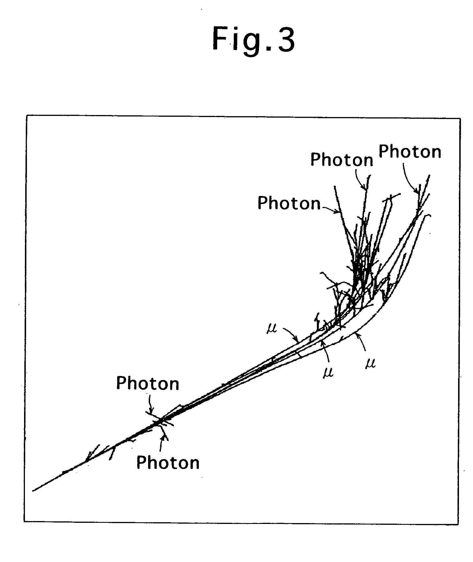
[0022] A muon decays into either an electron, a neutrino and an antineutrino or a positron, a neutrino and an antineutrino, according to the following decay schemes.

μ+→e+νe{overscore (ν)}μ

μ−→e−{overscore (ν)}eνμ[0023]μ+: Positive muon [0024]μ−: Negative muon [0025] e+: Positron [0026] e−: Electron [0027]νe: Electron neutrino [0028]νμ: Muon neutrino

[0029] The upperl...


PUM


Abstract

A method for triggering of lightning discharge which is high in lightning triggering efficiency and capable of surely triggering lightning discharge is provided. The method comprises collimating muons emitted from a high energy proton or electron accelerator, and irradiating the collimated muon beam toward a thundercloud to thereby promote ionization of air in the thundercloud and trigger lightning discharge. An apparatus for implementing the method for triggering of lightning is also provided. The apparatus comprises a high energy proton or electron accelerator from which a proton beam or an electron beam is emitted, a target from which pions are emitted by irradiating the target with the proton or electron beam, a collimator for collimating muons generated by the decay of the pions, and an accelerating tube for accelerating the collimated muon beam and irradiating the muon beam toward a thundercloud.

Description

FIELD OF THE INVENTION [0001] The present invention relates to a method for artificial triggering of lightning discharge in which lightning discharge is triggered within a thundercloud to dissipate energy through the discharge and alleviate the damage caused by lightning strikes to ground facilities and persons, and an apparatus for artificial triggering of lightning discharge for implementing the method. BACKGROUND OF THE INVENTION [0002] As a method for triggering lightning discharge, there have hitherto been proposed a method for triggering of lightning discharge using a rocket in which a rocket having a stretching metal wire is launched toward a thundercloud (see, for example, M. M. Newman et al., J. Geophys. Res., 72, 4761-4764 (1967)) and a method for triggering of lightning discharge using a laser in which a laser beam is irradiated toward a thundercloud and plasma generated in air by the laser beam is utilized to trigger lightning (see, for example, L. M. Ball, Appl. Opt., 1...

Claims


Application Information

Patent Timeline
Patent Type & Authority Applications(United States)
IPC IPC(8): G21K5/04H02H1/04H05F3/04H05H9/00
CPCH05H6/00
Inventor TORII, TATSUO
Owner JAPAN NUCLEAR CYCLE DEV INST
Learn More