

Optical modulator and communications system
a technology of optical modulator and communication system, applied in the field of optical modulator, can solve the problems of difficult to carry out ultrahigh speed light modulation by a conventional direct modulation technique, the velocities of these two waves cannot match each other, and the electro-optic constant of lithium niobate crystals is very small, so as to achieve high modulation efficiency
- Summary
- Abstract
- Description
- Claims
- Application Information
AI Technical Summary
Benefits of technology
Problems solved by technology
Method used
Image

Examples
embodiment 1
[0052] Embodiment 1
[0053] A first preferred embodiment of an optical modulator according to the present invention will be described.
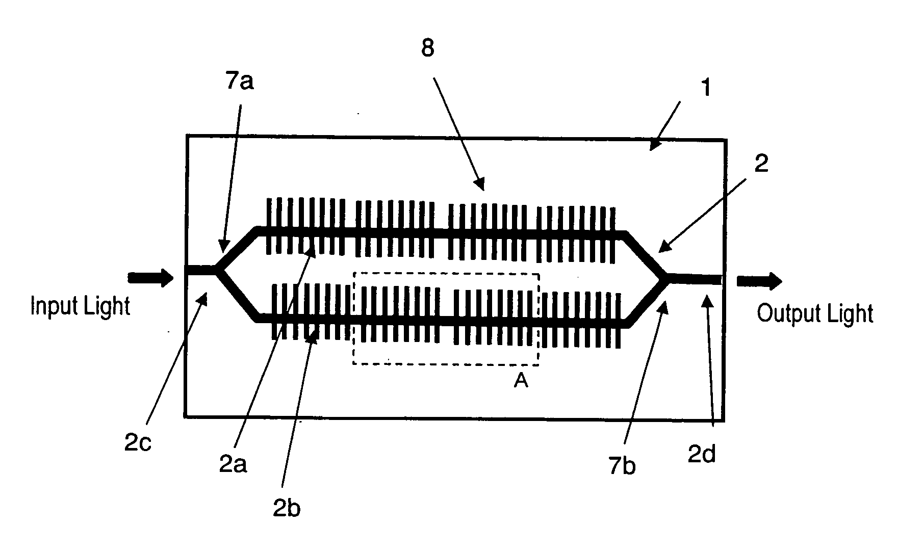
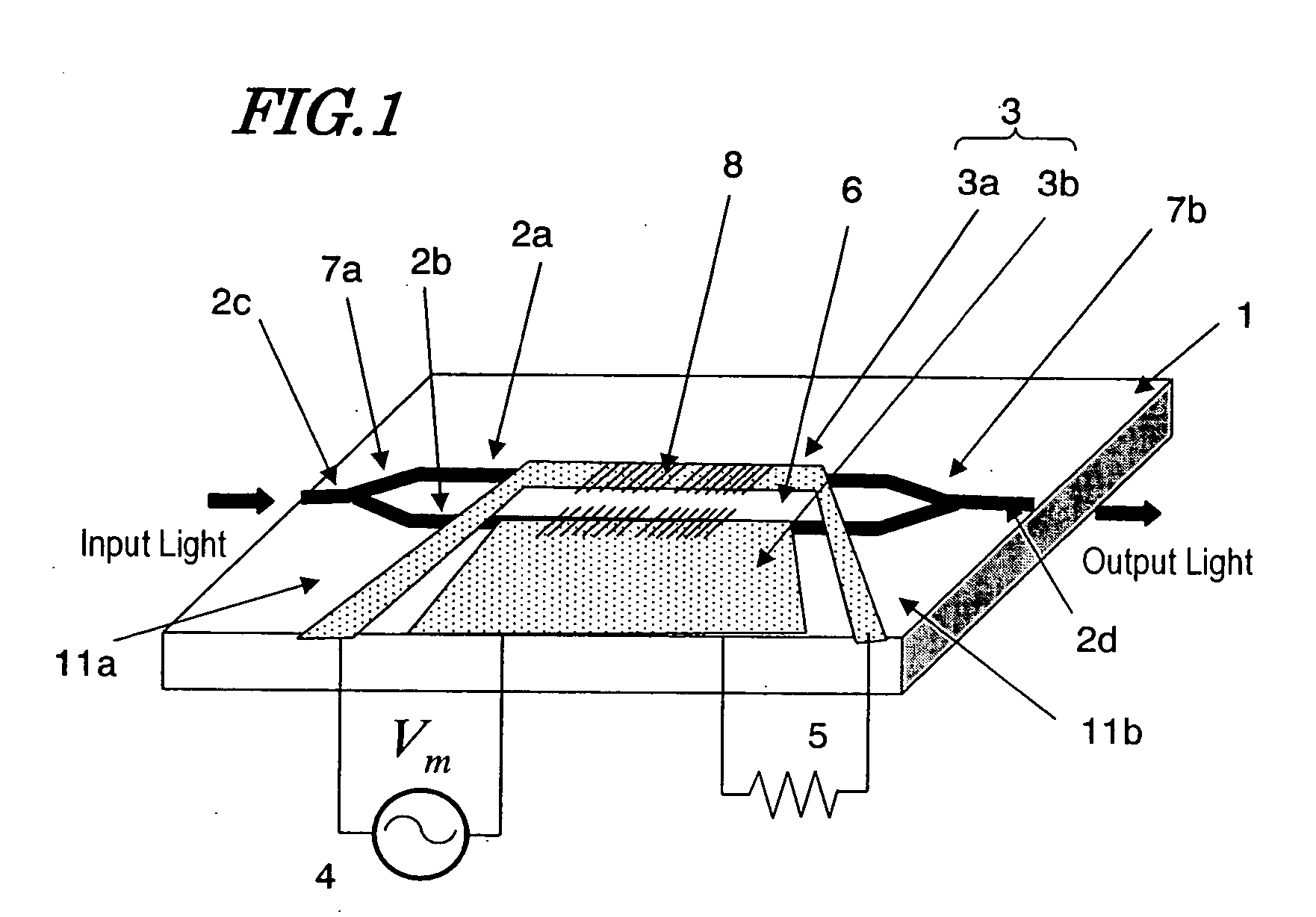
[0054] First, referring to FIG. 1, illustrated is an optical modulator according to this preferred embodiment, which includes an optical waveguide 2a to 2d made of a material with an electro-optic effect and a modulating electrode 3 for applying a modulating electric signal (which will be referred to herein as a “modulating wave”) to a light wave propagating through the optical waveguide 2a to 2d. The optical modulator of this preferred embodiment is characterized by further including a periodic structure, of which the equivalent refractive index changes periodically in the light propagation direction. This prominent feature will be described more fully later.
[0055] Just like the conventional optical modulator described above with reference to FIG. 14, the optical waveguide 2a to 2d of this preferred embodiment also includes an optical input portion 2...
embodiment 2
[0085] Embodiment 2
[0086] Hereinafter, a second preferred embodiment of an optical modulator according to the present invention will be described.
[0087] The optical modulator of this preferred embodiment has the same configuration as the counterpart of the first preferred embodiment described above except the periodic structure provided for the optical waveguide. Thus, the following detailed description will be focused on the periodic structure of this preferred embodiment but the other portions will not be described again.
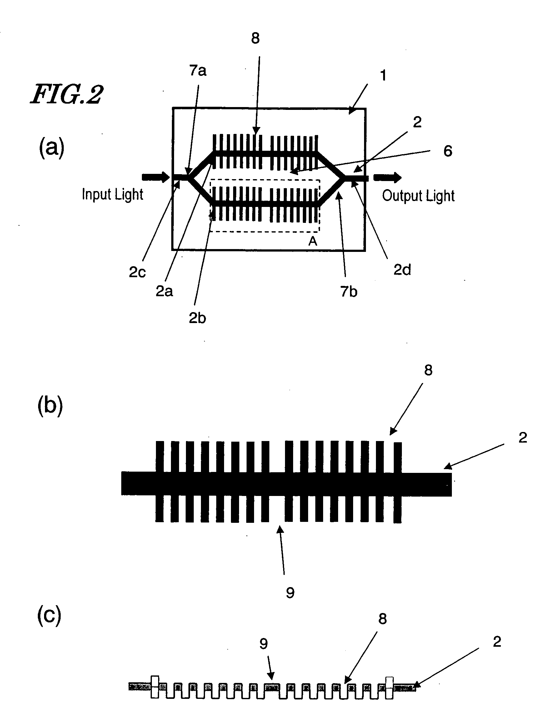
[0088] As mentioned above, the depth, width and interval of the grooves 8 are controllable by adjusting the specific pattern of the etching mask and the conditions of the etching process. And by modifying the depth, width and interval of the grooves 8, the group velocity characteristic of the light waves propagating through the optical waveguide 2 can be controlled.
[0089] Supposing the free space velocity of a light wave is represented by v0 and the refractive ...
embodiment 3
[0103] Embodiment 3
[0104] Hereinafter, a third preferred embodiment of an optical modulator according to the present invention will be described with reference to FIG. 5.
[0105] Each of the preferred embodiments described above includes a Mach-Zehnder interferometer type optical waveguide and functions as a light intensity modulator that takes advantage of interference. On the other hand, the optical modulator of this preferred embodiment includes a single optical waveguide 2, along which the same grooves 8 as the counterparts of the preferred embodiments described above are arranged as shown in FIG. 5.
[0106] The optical modulator of this preferred embodiment can also reduce the group velocity of the light waves propagating through the optical waveguide 2. Thus, by getting a modulating electric field applied from a modulating electrode (not shown) to the optical waveguide 2, the optical modulator can operate as a small-sized optical phase modulator with high modulation efficiency. ...
PUM
 Abstract
Description
Claims
Application Information