Variable geometry resonator for acoustic control

a resonator and variable geometry technology, applied in the field of resonators, can solve the problems of induction noise, insufficient frequency range to attenuate the various noise frequencies produced by the engine, and the air induction system of internal combustion engines producing undesirable nois

Inactive Publication Date: 2005-09-15
HANON SYST
View PDF14 Cites 39 Cited by
  • Summary
  • Abstract
  • Description
  • Claims
  • Application Information

AI Technical Summary

Benefits of technology

[0006] In satisfying the above need, as well as overcoming the enumerated drawbacks and other limitations of the related art, the present invention provides a resonator for attenuating acoustic pressure pulsations from an air intake passage. The resonator includes a neck, a resonator chamber, a piston-type member, and an actuator. The neck, attached between the air passage and the

Problems solved by technology

The air induction systems of internal combustion engines produce undesirable noise in the form of acoustic pressure pulsations.
The induction noise is caused by a pressure wave that travels from th

Method used


Image

  • Variable geometry resonator for acoustic control
  • Variable geometry resonator for acoustic control
  • Variable geometry resonator for acoustic control

Examples


Embodiment Construction

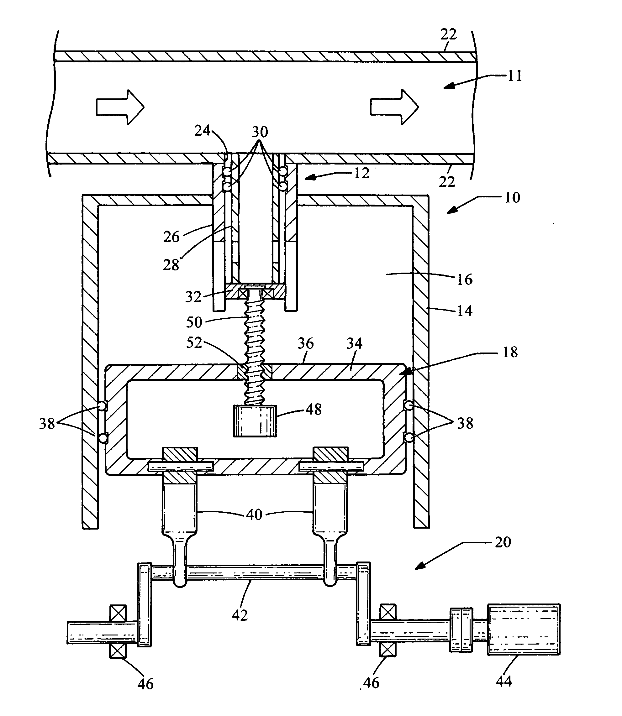
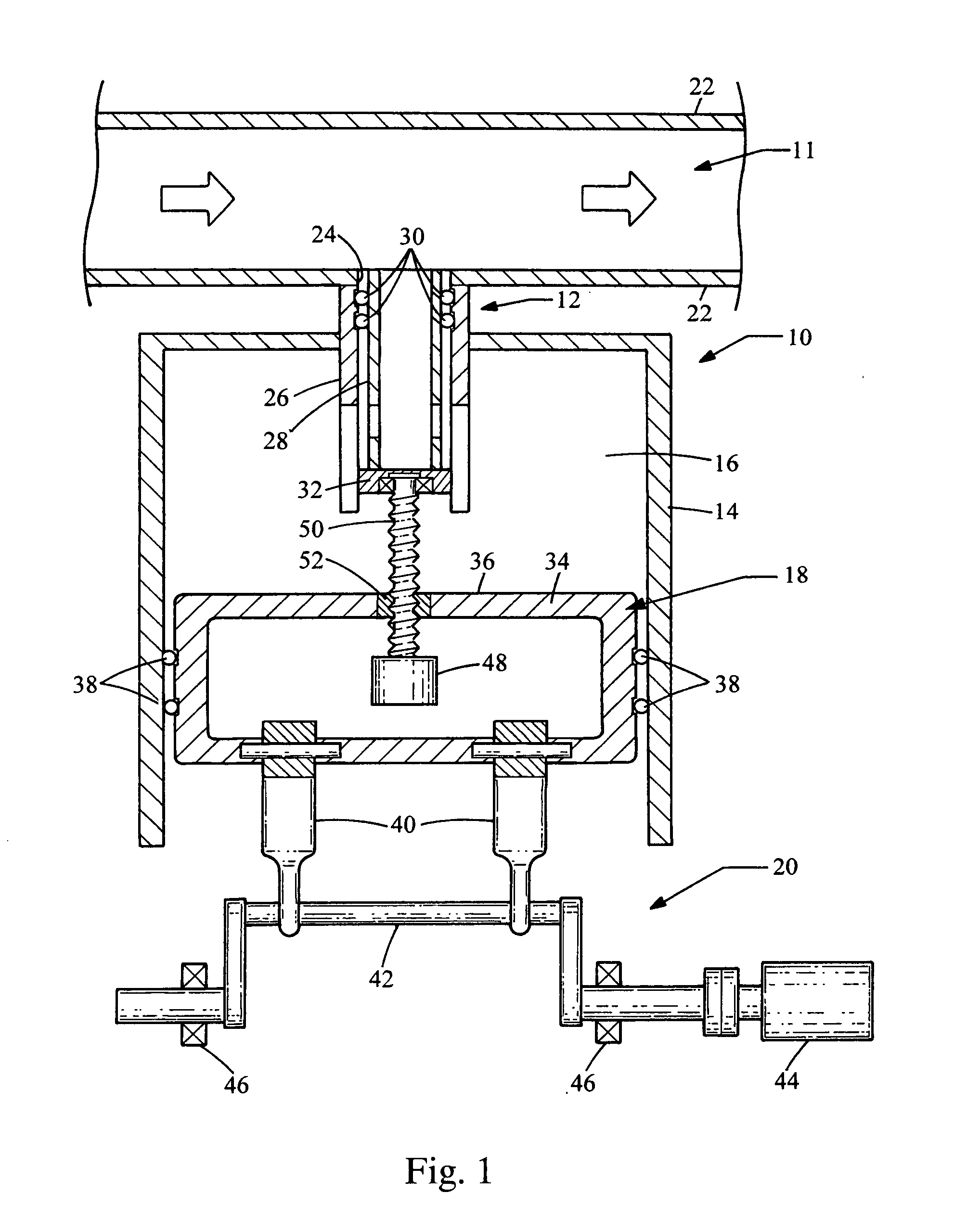
[0012] Now referring to FIG. 1, a resonator embodying the principles of the present invention is illustrated therein and designated at 10. The resonator 10 includes a neck 12, a resonator chamber 16, a member 18 and a actuator 20. The neck 12 is attached to an opening 24 in the walls 22 of an air intake 11.

[0013] Air flows through the air intake 11, part of the air induction system, to an engine (not shown). As an effect of the operation of the engine, a noise wave travels from the engine back through the air intake 11. Being coupled to the air intake 11, the resonator 10 attenuates the noise wave by reflecting the noise wave to the air intake 11 with a phase shift, thereby producing a canceling effect. The configuration shown where the noise wave enters and exits the resonator through the neck 12 is considered a side branch configuration.

[0014] The neck 12 has an outer wall 26 and an inner wall 28, with the outer wall 26 being stationary and the inner wall 28 being extendable int...


PUM


Abstract

The present invention provides a resonator for attenuating acoustic vibration from an air intake passage. The resonator includes a neck, a resonator chamber, a piston-type member, and an actuator. The neck is attached between the air passage and the resonator chamber. The neck has two overlapping portions allowing the neck to extend within the resonator chamber. The piston-type member is located within the resonator chamber and is translated by the actuator to change the volume of the resonator and the neck length. By changing the volume and neck length of the resonator, the frequency attenuated by the resonator can be adjusted.

Description

BACKGROUND [0001] 1. Field of the Invention [0002] The present invention generally relates to a resonator for attenuating acoustic pressure pulsations from an engine. [0003] 2. Description of Related Art [0004] Resonators for attenuating acoustic pressure pulsations in automotive applications are well known. The air induction systems of internal combustion engines produce undesirable noise in the form of acoustic pressure pulsations. This induction noise depends on the engine configuration and engine speed. The induction noise is caused by a pressure wave that travels from the inlet valve towards the inlet of the air induction system. The induction noise may be reduced by reflecting a wave toward the inlet valve 180° out of phase with the noise wave. As such, Helmholtz type resonators have been used to attenuate the noise wave generated from the inlet valve-opening event. In addition and more recently, resonators have been developed that change the volume of the resonator to adjust ...

Claims


Application Information

Patent Timeline
IPC IPC(8): F01N1/02F01N1/08
CPCF02M35/1261
Inventor GOENKA, LAKHI N.MOENSSEN, DAVID J.KOSTUN, JOHN D.SHAW, CHRISTOPHER E.
Owner HANON SYST
Why Eureka
Try Eureka