Semiconductor device
a technology of semiconductor devices and insulating films, applied in semiconductor devices, semiconductor/solid-state device details, electrical devices, etc., can solve the problems of low mechanical strength of porous insulating films, low mechanical strength and low adhesion of interlayer insulating films
- Summary
- Abstract
- Description
- Claims
- Application Information
AI Technical Summary
Benefits of technology
Problems solved by technology
Method used
Image
Examples
first embodiment
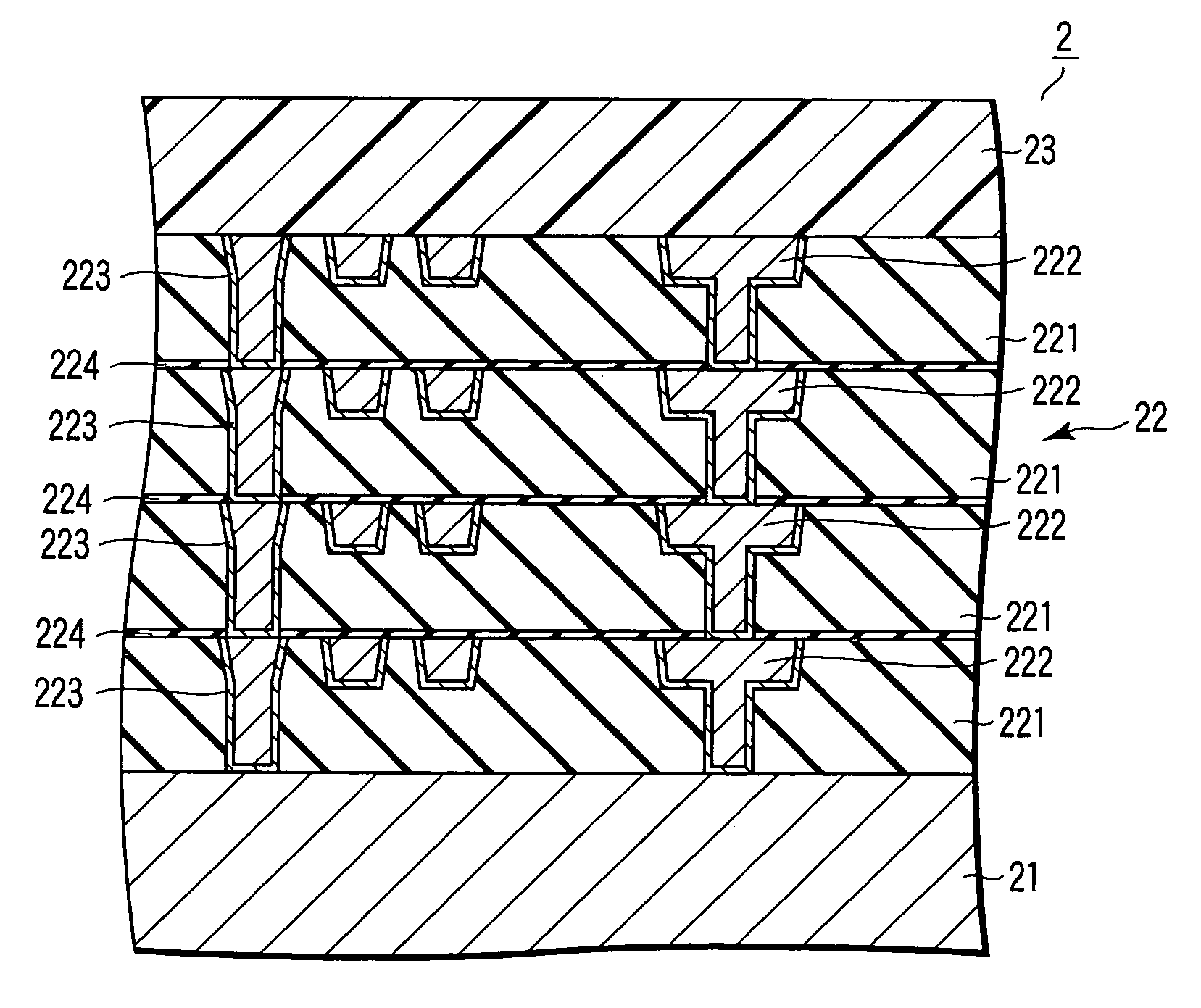
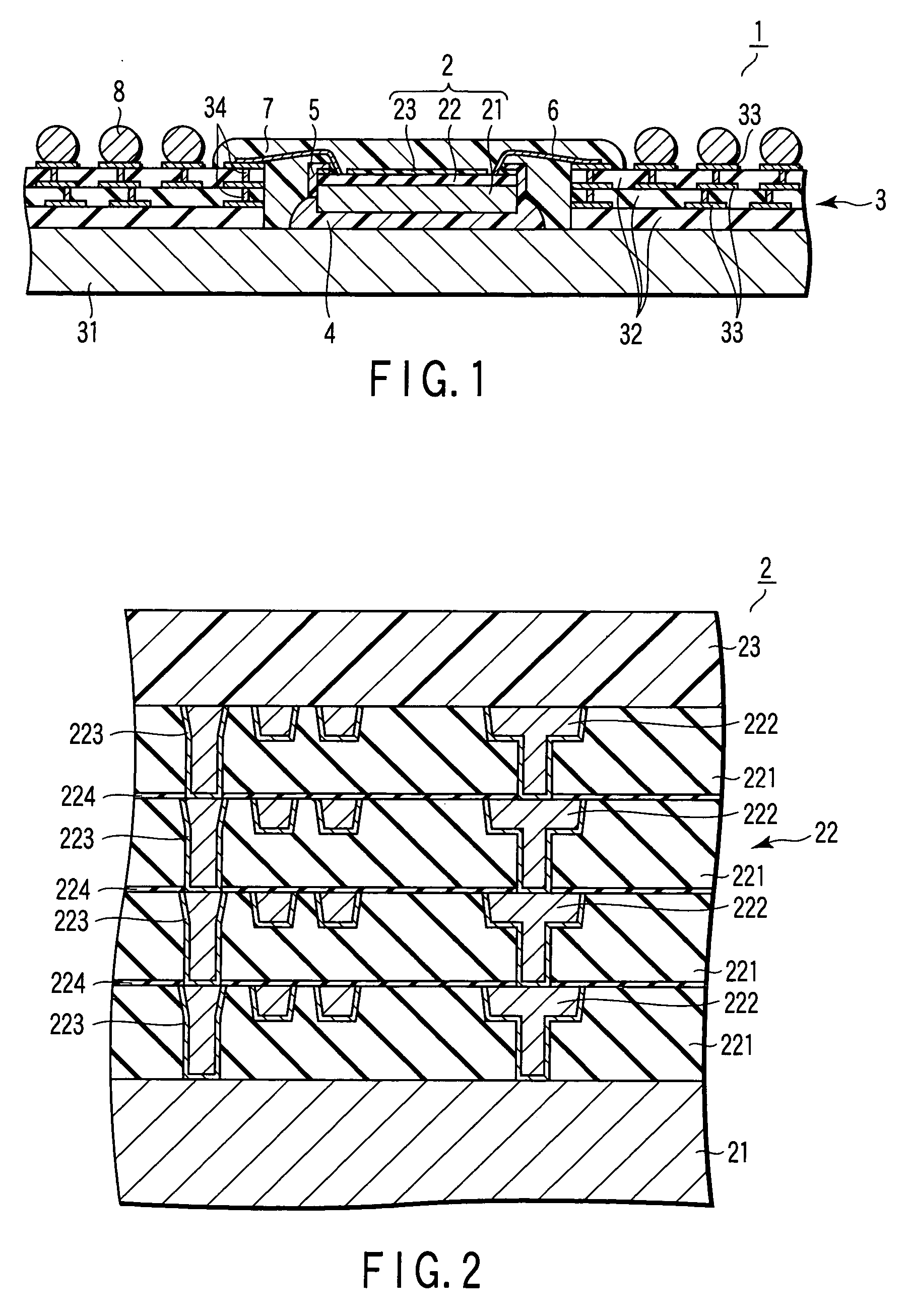
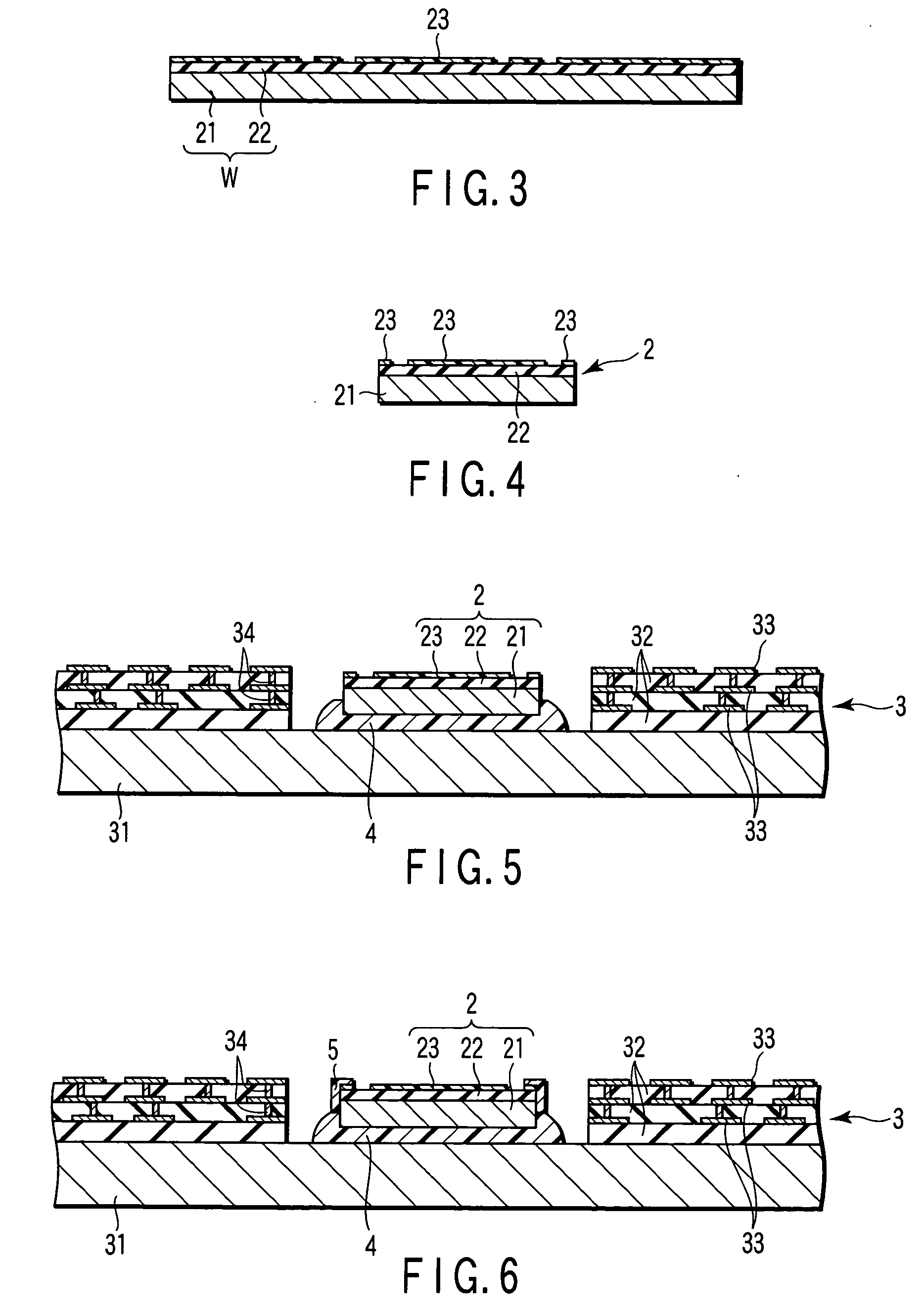
[0022]FIG. 1 is a sectional view schematically showing a semiconductor device according to the present invention. FIG. 2 is a sectional view schematically showing an example of a semiconductor chip usable in the semiconductor device shown in FIG. 1.
[0023] The semiconductor device 1 shown in FIG. 1 is a semiconductor package called an enhanced ball grid array (EBGA). The semiconductor package 1 includes a semiconductor chip 2, a wiring substrate 3, a mounting material 4, a stress relaxing resin layer 5, bonding wires 6, a resin encapsulating layer 7, and metal bumps 8.
[0024] The semiconductor chip 2 includes a semiconductor substrate 21 such as a silicon substrate. Various elements such as transistors are formed on one major surface of the semiconductor substrate 21.
[0025] A multilayer interconnection structure 22 is formed on this major surface of the semiconductor substrate 21. The multilayer interconnection structure 22 includes a plurality of interlayer insulating films 221 and...
second embodiment
[0052] the present invention will be described below.
[0053]FIG. 9 is a sectional view schematically showing a semiconductor device according to the second embodiment of the present invention. A semiconductor device 1 has the same structure as the semiconductor package 1 according to the first embodiment except that a stress relaxing resin layer 5 covers the edges of a semiconductor chip 2 on the side of a multilayer interconnection structure 22 and covers a central portion of the major surface of the semiconductor chip 2 on the side of the multilayer interconnection structure 22. When this structure is used, the same effects as explained in the first embodiment can be obtained.
[0054] Also, in the semiconductor package 1 shown in FIG. 9, the stress relaxing resin layer 5 covers the central portion of the major surface of the semiconductor chip 2 on the side of the multilayer interconnection structure 22. When this structure is used, a larger amount of material is necessary to form t...
third embodiment
[0055] the present invention will be described below.
[0056]FIG. 10 is a sectional view schematically showing a semiconductor device according to the third embodiment of the present invention. A semiconductor device 1 has the same structure as the semiconductor package 1 according to the first embodiment except that the buffer coating layer 23 is omitted. When this structure is used, almost the same effects as explained in the first embodiment can be obtained.
[0057] Since the buffer coating layer 23 is omitted from the semiconductor package 1 shown in FIG. 10, a stress larger than that in the semiconductor package 1 of the first embodiment acts on a central portion of the major surface of the semiconductor chip 2 on the side of the multilayer interconnection structure 22. However, the semiconductor package 1 shown in FIG. 10 is more advantageous in reducing the fabrication cost than the semiconductor package 1 of the first embodiment.
PUM
 Abstract
Description
Claims
Application Information
 - R&D
- Intellectual Property
- Life Sciences
- Materials
- Tech Scout
- Unparalleled Data Quality
- Higher Quality Content
- 60% Fewer Hallucinations
Browse by: Latest US Patents, China's latest patents, Technical Efficacy Thesaurus, Application Domain, Technology Topic, Popular Technical Reports.
© 2025 PatSnap. All rights reserved.Legal|Privacy policy|Modern Slavery Act Transparency Statement|Sitemap|About US| Contact US: help@patsnap.com


