Enamel resin-insulating laminate, inverter surge-resistant insulated wire using the same and electric/electronic equipment

a technology of insulating wire and resin, which is applied in the direction of insulating conductors/cables, cables, insulated conductors, etc., can solve the problems of low voltage decay due to connection cables, high steep voltage rise, and high surge voltage, so as to improve the voltage in the initial voltage of partial discharge, improve the effect of dielectric breakdown and thermal aging-resistant properties

Active Publication Date: 2019-09-17
ESSEX FURUKAWA MAGNET WIRE LLC
View PDF38 Cites 1 Cited by
  • Summary
  • Abstract
  • Description
  • Claims
  • Application Information

AI Technical Summary

Benefits of technology

[0034]The enamel resin-insulating laminate (hereinafter, referred to as “shaped object” in several cases) of the present invention is small in a dielectric constant, and when the laminate is used as an insulating layer of the insulated wire, the laminate can significantly contribute to an improvement in a partial discharge inception voltage, dielectric breakdown properties and thermal aging-resistant properties.
[0035]Moreover, the inverter surge-resistant insulated wire and the electric and electronic equipment according to the present invention in which the enamel resin-insulating laminate of the present invention is provided as the insulating layer are high in partial discharge inception voltage as well as dielectric breakdown voltage and have excellent thermal aging-resistant properties.
[0036]Other and further features and advantages of the invention will appear more fully from the following description, appropriately referring to the accompanying drawings.

Problems solved by technology

In particular, an output pulse occurred due to a high-speed switching device, such as an IGBT, is high in steep voltage rise.
Accordingly, even if a connection cable is short, the surge voltage is high, and voltage decay due to the connection cable is also low.
However, this method has a drawback that the solvent of the varnish dose not completely vaporize and remains in the enamel layer as voids.
Even if the insulating layer of an insulated wire is formed using the synthetic resin described in Patent Literature 3, the performance is far from fully satisfactory in view of the partial discharge inception voltage, the insulation performance and thermal aging resistance under high temperature.

Method used


Image

  • Enamel resin-insulating laminate, inverter surge-resistant insulated wire using the same and electric/electronic equipment
  • Enamel resin-insulating laminate, inverter surge-resistant insulated wire using the same and electric/electronic equipment
  • Enamel resin-insulating laminate, inverter surge-resistant insulated wire using the same and electric/electronic equipment

Examples


example 1

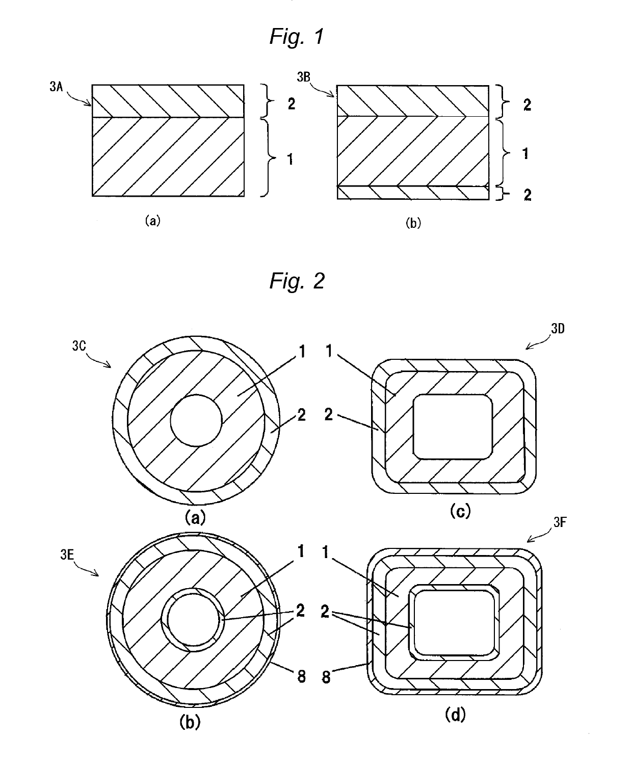
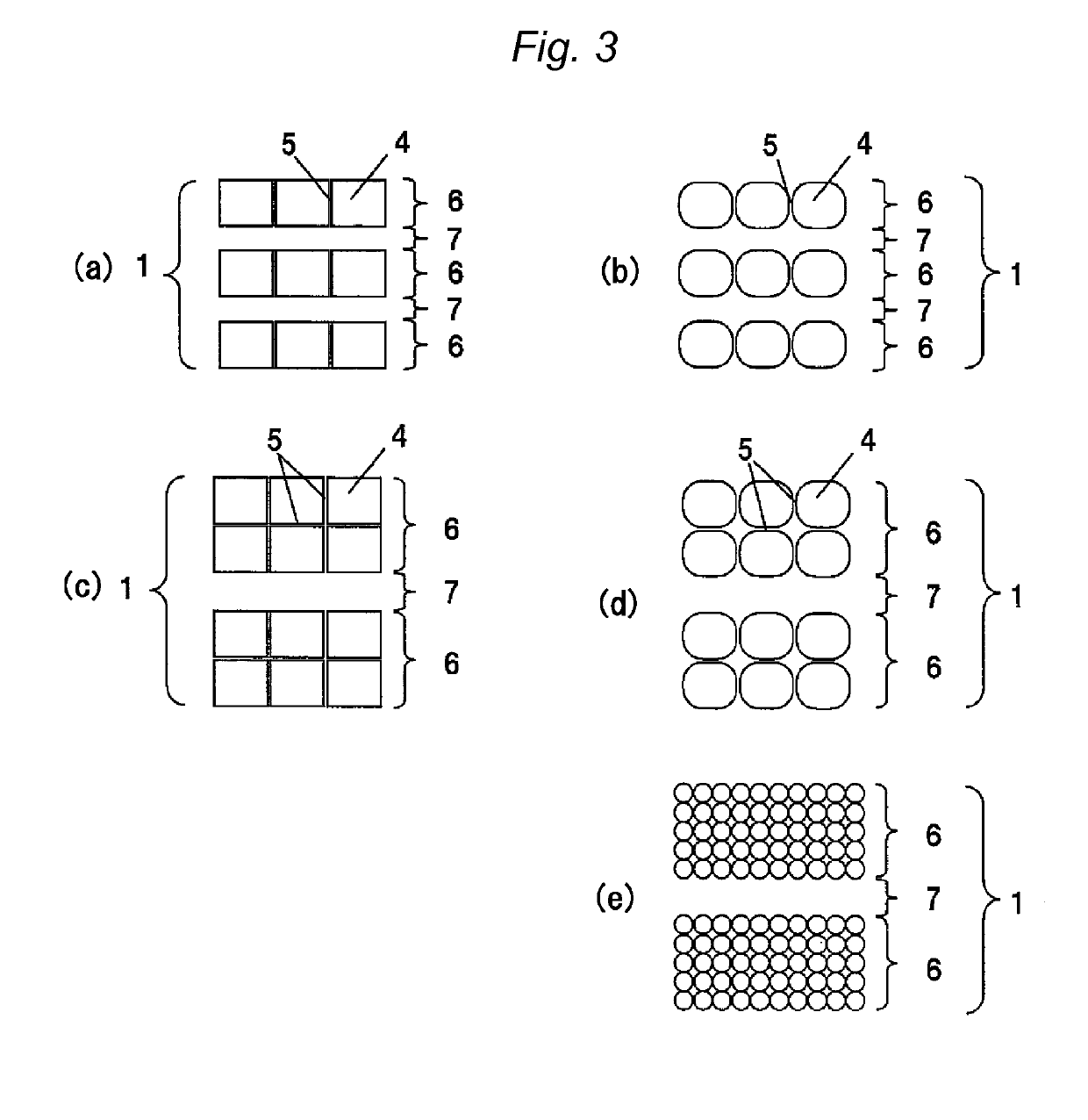
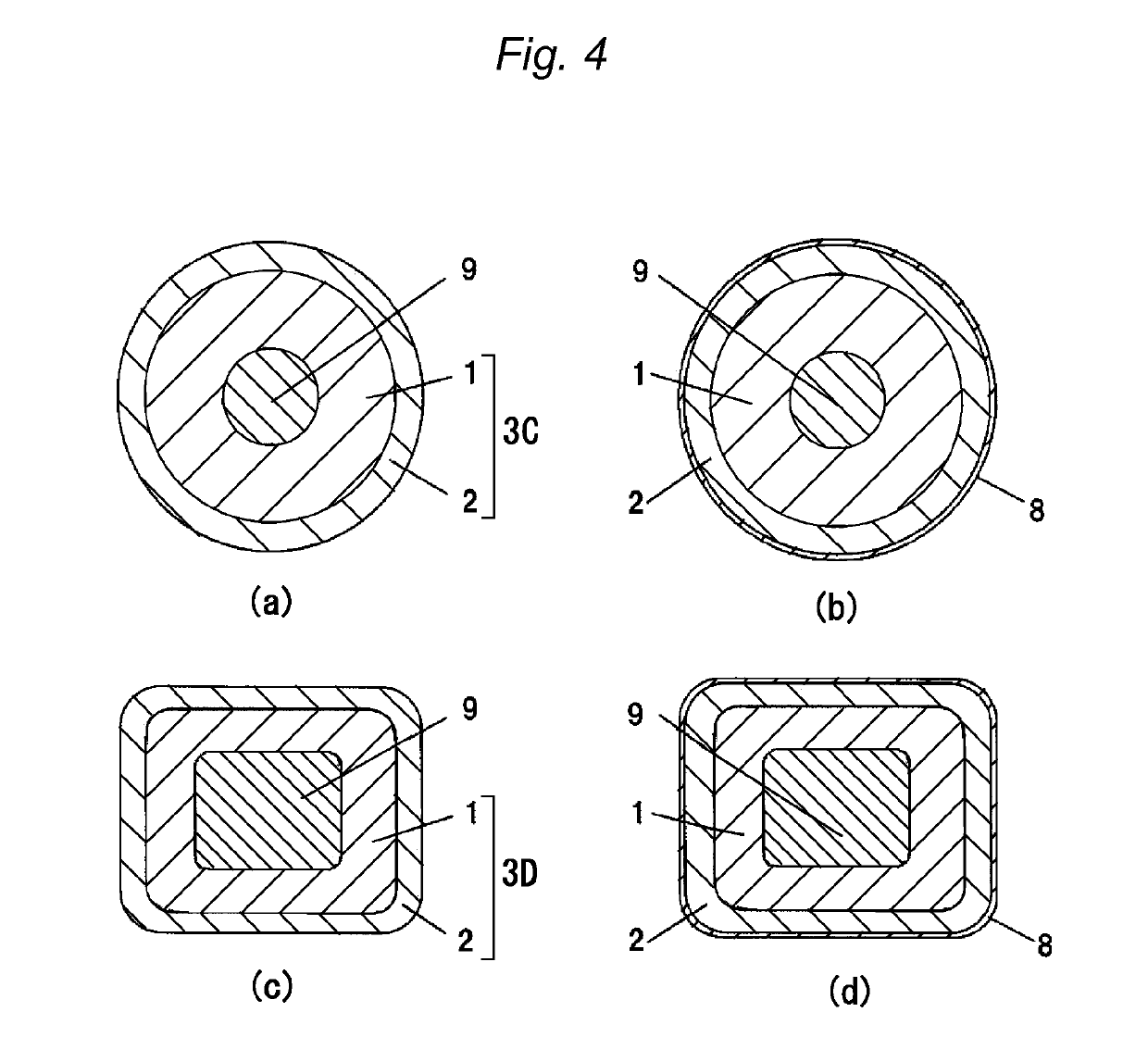
[0137]In Example 1, the insulated wire shown in FIG. 4(a) was produced. The insulated wire had an enamel resin-insulating laminate including foamed region 1 and non-foamed region 2, foamed region 1 having double-layered cell layers 6 and single-layered non-cell layer 7 as shown in FIG. 3(d).

[0138]Specifically, PAI varnish (A) for cell formation was applied onto the periphery of copper wire (conductor) 9 having a diameter of 1 mm, and the resultant material was baked once at a furnace temperature of 520° C. for 20 seconds to form cell layer 6 on the conductor. Onto the periphery of the thus formed cell layer 6, PAI varnish (HI-406 (trade name), a solution containing 33% by mass of resin component, manufactured by Hitachi Chemical Co., Ltd.) was applied, and the resultant material was baked twice for 20 seconds to form non-cell layer 7, and onto the periphery of non-cell layer 7, PAI varnish (A) for cell formation was applied, and the resultant material was baked once for 20 seconds t...

example 2

[0139]The insulated wire shown in FIG. 4(a) was produced in a manner similar to the procedure in Example 1 except that PAI varnish (C) for cell formation was baked at a furnace temperature of 500° C. in place of PAI varnish (A) for cell formation.

example 3

[0140]The insulated wire shown in FIG. 4(a) was produced in a manner similar to the procedure in Example 1 except that an enamel resin-insulating laminate including foamed region 1 and non-foamed region 2 as shown in FIG. 3(b) was formed by baking PAI varnish (A) for cell formation three times and by baking PAI varnish (E) twice in terms of times of baking.


PUM

PropertyMeasurementUnit
porosityaaaaaaaaaa
porosityaaaaaaaaaa
relative dielectric constantaaaaaaaaaa

Abstract

An inverter surge-resistant insulated wire comprising a conductor and an enamel resin-insulating laminate that has a foamed region including cells and a non-foamed region including no cells on at least one surface of the foamed region on the conductor, wherein the foamed region is configured such that a non-cell layer including no cells has cell layers formed of closed cells on both surface sides of the non-cell layer, a thickness of the non-cell layer is larger than a thickness of a partition wall among the closed cells, and 5 to 60% of a thickness of the foamed region, and at least 10 the cell layer in the foamed region is formed of a thermosetting resin; an inverter surge-resistant insulated wire having a conductor and the enamel resin-insulating laminate; and electric / electronic equipment.

Description

CROSS-REFERENCE TO RELATED APPLICATIONS[0001]This application is a continuation of PCT / JP2014 / 052574 filed on Feb. 4, 2014 which claims priority on Japanese Patent Application No. 2013-022742 filed on Feb. 7, 2013, the subject matter of which is incorporated herein by reference in their entirety.TECHNICAL FIELD[0002]The present invention relates to an enamel resin-insulating laminate, an insulated wire using the same and electric / electronic equipment.BACKGROUND ART[0003]In electric and electronic equipment in recent years, specifically, a radio-frequency printed board or inverter-related equipment, for example, a fast switching device, an inverter motor or an electric equipment coil for a transformer or the like, demands have been made for further improving various kinds of performance, for example, heat resistance, mechanical properties, chemical properties, electric properties and reliability in comparison with a conventional product. For such electric and electronic equipment, an...

Claims


Application Information

Patent Timeline
Patent Type & Authority Patents(United States)
IPC IPC(8): B32B7/02H02K3/30H01B3/30H01B13/06H01B7/02H01B7/29H01F5/06
CPCH02K3/30H01B13/065H01B7/29H01B3/306H01B7/02H01B3/308Y10T428/2935H01F5/06Y10T428/24975Y10T428/2495
Inventor MUTO, DAISUKEOYA, MAKOTOTOMIZAWA, KEIICHI
Owner ESSEX FURUKAWA MAGNET WIRE LLC
Why Eureka
Try Eureka