High pressure resistant insulation supporting post containing tightly packaged fiber as well as manufacture and application thereof

A technology of tight-packed optical fibers and insulating pillars, applied in insulators, transformers, voltage/current isolation, etc., can solve the problems of uneven thickness, decreased polarization transmission performance stability of tight-packed optical fibers, and no longer suitable for data transmission channels, etc. Achieve the effect of high insulation performance index, stable polarized light transmission performance, excellent partial discharge and withstand voltage performance indicators

Inactive Publication Date: 2008-08-27
SHANGHAI MUNICIPAL ELECTRIC POWER CO +1
View PDF1 Cites 2 Cited by
  • Summary
  • Abstract
  • Description
  • Claims
  • Application Information

AI Technical Summary

Problems solved by technology

[0012] Although the above three insulating pillars contain tight-packed optical fibers, they all have the following defects: in the preparation process of the insulating pillar, epoxy resin needs to be poured into the inner space of the insulating pillar, and after the epoxy resin is cured, the resulting Stress, acting on the tight-packed fiber, has a bad influence on the tight-packed fiber, making it uneven in thickness, resulting in a decrease in the stability of the polarization transmission performance of the tight-packed fiber
Strictly speaking, the tight-packed optical fibers sealed in the above-mentioned insulating pillars are no longer suitable for data transmission channels of high-voltage current transformers.

Method used


Image

  • High pressure resistant insulation supporting post containing tightly packaged fiber as well as manufacture and application thereof

Examples


Embodiment 1

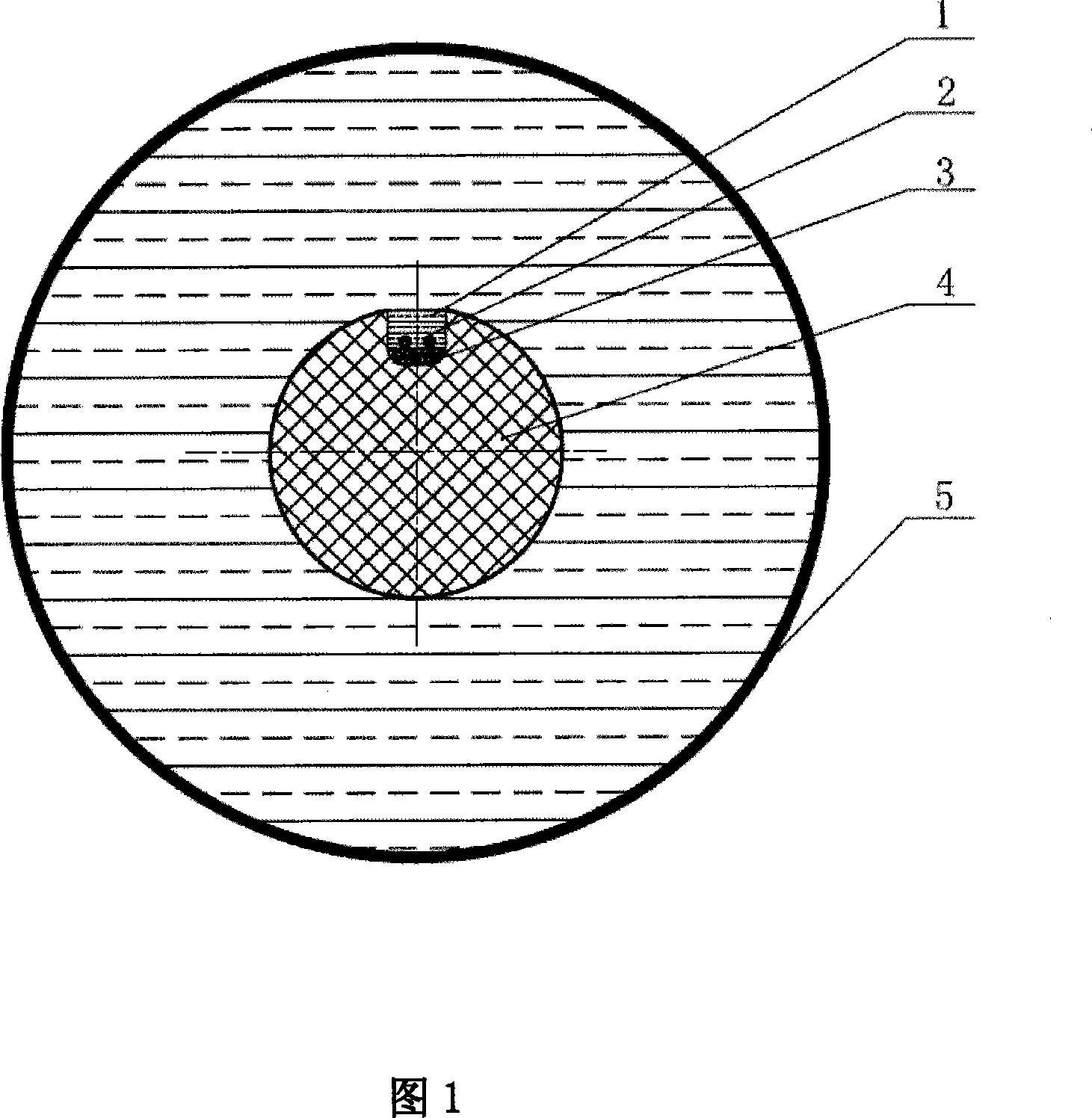
[0035] Embodiment 1: One of the high-voltage-resistant insulating pillars containing tightly-packed optical fibers. This embodiment has the structure shown in FIG. 1 .

[0036]A high-voltage insulating support with tight-packed optical fibers, including epoxy core rod 4, sealing fasteners, tight-packed optical fiber 2, epoxy resin 1 and insulating sleeve 5, epoxy core rod 4 is an insulating cylinder, and is placed in the ring The cylindrical surface of the oxygen mandrel 4 is provided with a groove parallel to the central axis of the epoxy mandrel 4, and runs through the two ends of the epoxy mandrel 4. There are sealing fasteners at both ends of the epoxy mandrel 4, and in the groove Two tight-packed optical fibers 2 are placed side by side on the bottom of the groove, and the two ends of each tightly-packed optical fiber 2 respectively pass through the corresponding small holes on the end surface of the sealed fastener and pass through the end surface of the sealed fastener....

Embodiment 2

[0037] Embodiment 2: The second high-voltage-resistant insulating pillar containing tightly-packed optical fibers. This embodiment has the structure shown in FIG. 1 . This embodiment is identical to Embodiment 1 except for the following differences: the width and depth of the groove are 10 mm and 10 mm, respectively.

Embodiment 3

[0038] Embodiment 3: The third high-voltage-resistant insulating pillar containing tightly-packed optical fibers. This embodiment has the structure shown in FIG. 1 . This embodiment is identical to Embodiment 1 except for the following differences: buffer glue 3 is D04(L)RTV silicone rubber.


PUM

PropertyMeasurementUnit
depthaaaaaaaaaa
depthaaaaaaaaaa

Abstract

The present invention discloses a high-voltage resistant insulation strut comprising tight coated fibers, and a manufacture and an application thereof, belonging to the technical field of the high-voltage resistant insulation strut in electrical power transmission and the manufacture and application thereof. The insulation strut comprises an epoxy core rod, sealing fasteners, tight coated fibers, epoxy resin, an insulation sleeve and cushioning liquid cement. The two ends of the epoxy core rod are provided with a sealing fastener respectively, and the epoxy core rod is provided with a groove which runs through the two ends. Two tight coated fibers are parallelly arranged in the groove. The two ends of each tight coated fiber traverse through end surfaces of the two sealing fasteners respectively. The groove is filled with the cushioning liquid cement. The epoxy core rod is arranged in the insulation sleeve in such a manner that the central axis is overlapped with the central axis of the insulation sleeve. A space among the top of the cushioning liquid cement, the epoxy core rod and the insulation sleeve is filled with the epoxy resin. The strut has the advantages of high insulation performance index, high mechanical strength, good local discharge and voltage resistance performance and the performance of the tight coated fiber being not affected by outside stress. Particularly, the strut is suitable for being used as a data transmission channel for a high-voltage current transformer.

Description

technical field [0001] The present invention relates to a kind of high-voltage resistant insulation pillar containing tight-packed optical fiber and its manufacture and application. The technical field of high-voltage resistant insulation pillar in transportation and its manufacture and application. Background technique [0002] Optical fiber is the abbreviation of optical fiber waveguide or optical fiber. Its traditional structure is a cylinder and multiple cladding layers attached to its surface in turn. From the center to the outside are the core, cladding and coating. [0003] The core part is the core and the cladding. The core is made of highly transparent material and is the main transmission channel for light waves; the refractive index of the cladding is slightly smaller than that of the core, making the light transmission performance relatively stable. The thickness of the core, the refractive index of the core material and the cladding material have a decisive in...

Claims


Application Information

Patent Timeline
Patent Type & Authority Applications(China)
IPC IPC(8): G01R15/24H01F38/28H01F27/00H01B17/00
Inventor 曲焕亮杨建林一
Owner SHANGHAI MUNICIPAL ELECTRIC POWER CO
Why Eureka
Try Eureka