Analysis method and apparatus utilizing attenuated total reflection

a technology of total reflection and analysis method, which is applied in the field of attenuated total reflection analysis method and apparatus, can solve the problems of attenuated total reflection, low intensity of reflected light beam, and low intensity of total reflection from the interface between the dielectric material block and the metal film,

Inactive Publication Date: 2005-09-15
FUJIFILM CORP +1
View PDF4 Cites 28 Cited by
  • Summary
  • Abstract
  • Description
  • Claims
  • Application Information

AI Technical Summary

Benefits of technology

[0087] With the second analysis method and apparatus utilizing attenuated total reflection in accordance with the present invention, the image of the light beam, which has been totally reflected from the interface between the dielectric material block and the thin film layer, is detected with the photo detecting means and as the two-dimensional image constituted of the plurality of the pixels arrayed in the two-dimensional directions composed of the beam width direction and the incidence angle direction, which are perpendicular to each other. Also, the abnormal pixel row, which contains the pixel represented by the abnormal pixel data, is extracted from among the pixel rows, each of which extends in the incidence angle direction, in the array of the pixels constituting the two-dimensional image and in accordance with the output obtained from the photo detecting means, which has detected the two-dimensional image with respect to the reference sample having been supported by the analysis chip. Further, the position of the dark line is calculated with respect to the reference sample and in accordance with the pixel data corresponding to the pixel rows other than the abnormal pixel row, which has been extracted. Therefore, with the second analysis method and apparatus utilizing attenuated total reflection in accordance with the present invention, in cases where the dark line is deformed due to non-uniformity, and the like, of part of the optical path, a measurement result free from adverse effects of the deformation of the dark line is capable of being obtained.

Problems solved by technology

As a result, the intensity of the reflected light beam, which is totally reflected from the interface between the dielectric material block and the metal film, becomes markedly low.
Therefore, in such cases, the attenuated total reflection occurs, and the intensity of the light totally reflected from the aforesaid interface becomes markedly low.
However, in cases where the surface of the thin film layer of the analysis chip is not uniform, in cases where the sensing substance is not uniform, or in cases where staining occurs at part of the optical system, the problems often occur in that part of the dark line is deformed (for example, part of the dark line becomes dull).
Therefore, with the conventional analysis apparatus provided with the array-like photo detecting means, in cases where part of the dark line is deformed due to defects, such as non-uniformity, staining, and the like, of part of the analysis chip or part of the optical system, a measurement result containing adverse effects of the deformation of part of the dark line is obtained.
Accordingly, with the conventional analysis apparatus provided with the array-like photo detecting means, there is the possibility that the detection sensitivity will become low.

Method used


Image

  • Analysis method and apparatus utilizing attenuated total reflection
  • Analysis method and apparatus utilizing attenuated total reflection
  • Analysis method and apparatus utilizing attenuated total reflection

Examples


first embodiment

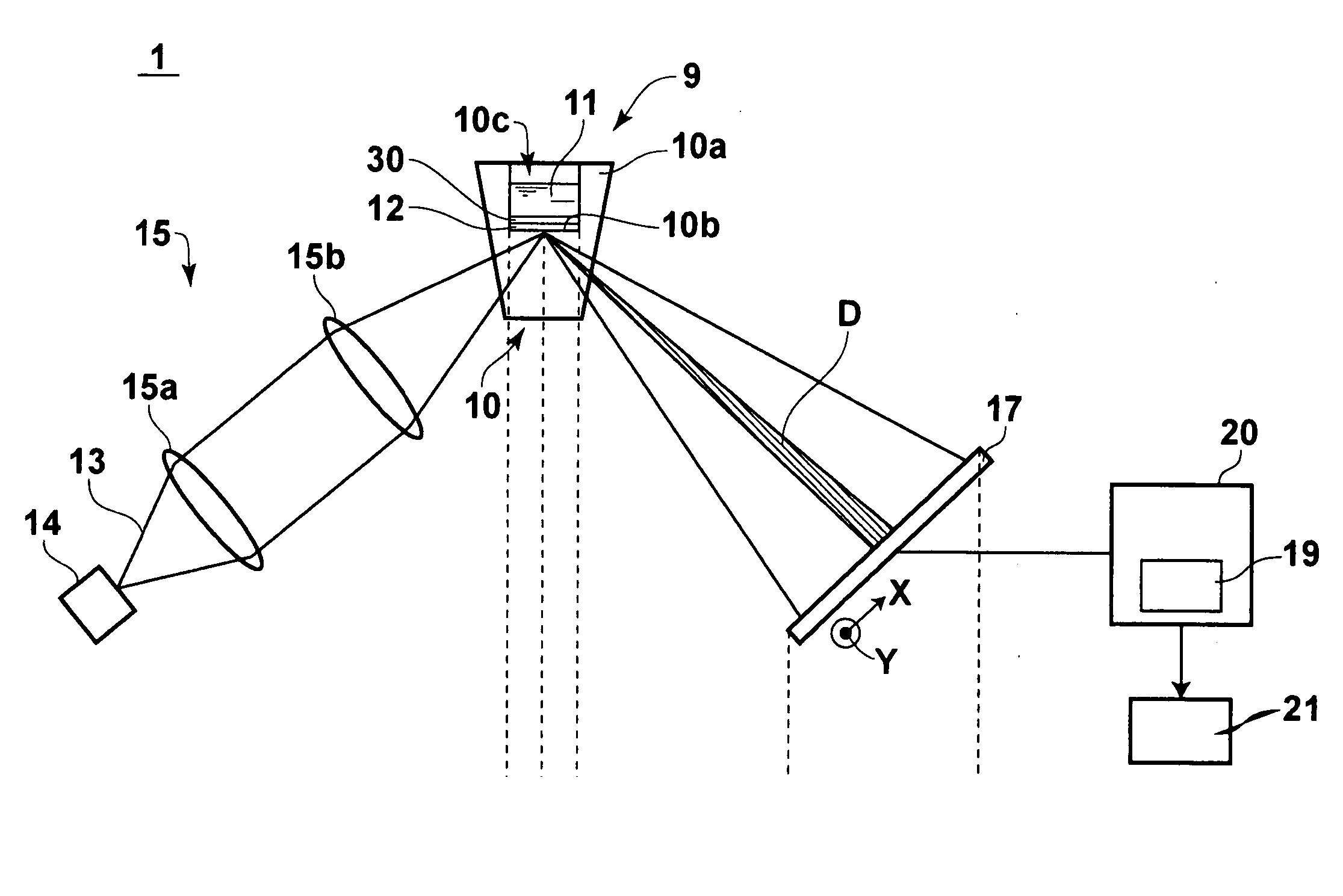
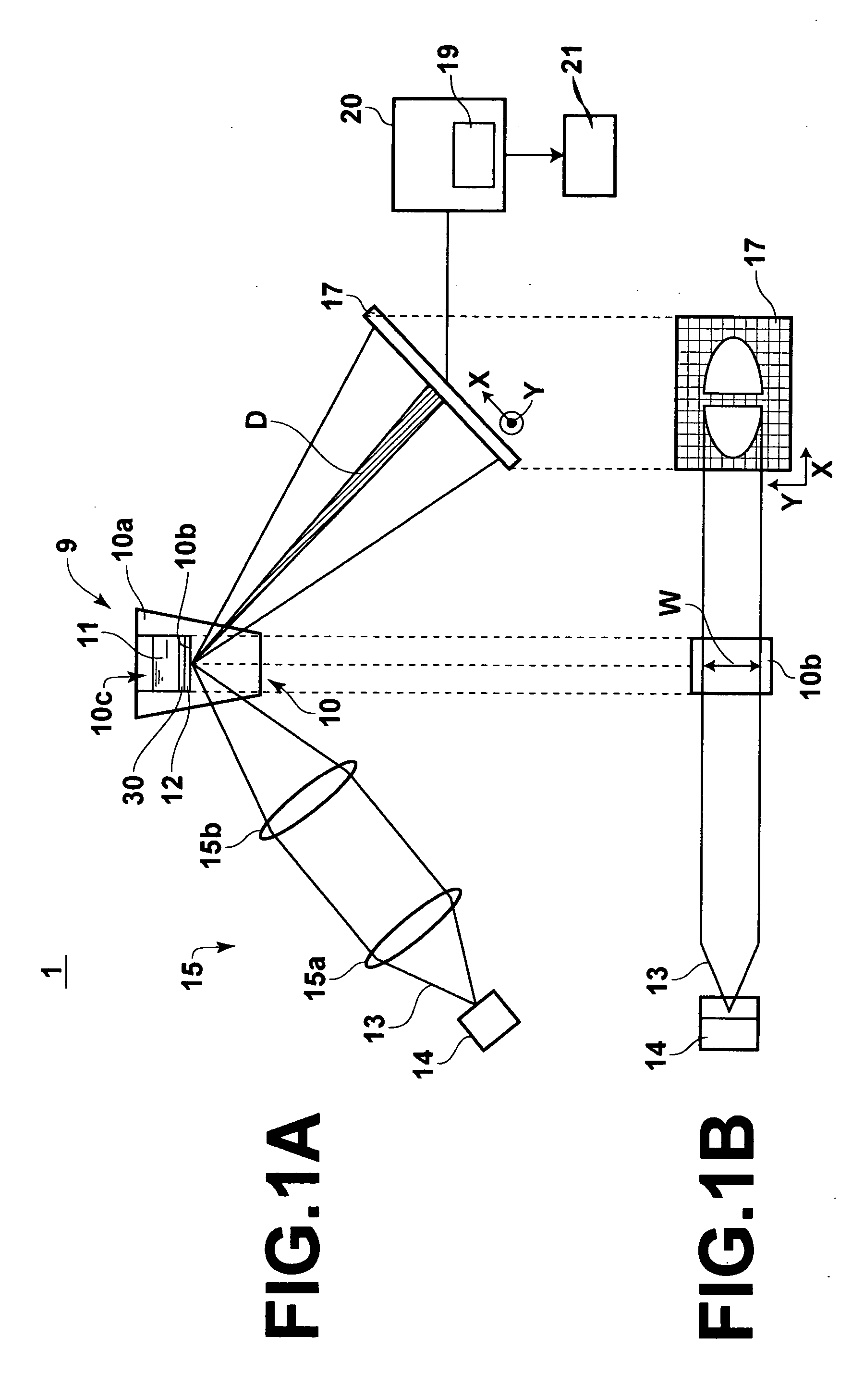
[0105]FIG. 1A is a schematic side view showing the analysis apparatus utilizing attenuated total reflection in accordance with the present invention, which is constituted as a surface plasmon resonance analysis apparatus. FIG. 1B is an explanatory plan view showing an optical path in the surface plasmon resonance analysis apparatus of FIG. 1A and an image formed by a light beam on a light receiving surface of photo detecting means.

[0106] With reference to FIG. 1A, a surface plasmon resonance analysis apparatus 1, which is the first embodiment of the analysis apparatus utilizing attenuated total reflection in accordance with the present invention, comprises an analysis chip 9. The surface plasmon resonance analysis apparatus 1 also comprises a laser beam source 14, which acts as a light source for producing a laser beam 13. The surface plasmon resonance analysis apparatus 1 further comprises a laser beam irradiating optical system 15 for irradiating the laser beam 13 to the analysis ...

second embodiment

[0140] the analysis apparatus utilizing attenuated total reflection in accordance with the present invention, which is constituted as a surface plasmon resonance analysis apparatus 101 and which is provided with different photo detecting means, will be described herein below. FIG. 5A is a schematic side view showing a second embodiment of the analysis apparatus utilizing attenuated total reflection in accordance with the present invention, which is constituted as the surface plasmon resonance analysis apparatus 101. FIG. 5B is an explanatory plan view showing a direction of movement of a light receiving section 71 of photo detecting means 70 utilized in the surface plasmon resonance analysis apparatus of FIG. 5A. In FIG. 5A, similar elements are numbered with the same reference numerals with respect to FIG. 1A.

[0141] With reference to FIG. 5A, the photo detecting means 70 is provided with the light receiving section 71, which comprises a plurality of light receiving devices 71a, 71a...

third embodiment

[0144] The surface plasmon resonance analysis apparatus described above may be constituted as a leaky mode analysis apparatus 201 through modification of part of the constitution. FIG. 6A is a schematic side view showing the analysis apparatus utilizing attenuated total reflection in accordance with the present invention, which is constituted as the leaky mode analysis apparatus 201. FIG. 6B is an explanatory plan view showing an optical path in the leaky mode analysis apparatus 201 of FIG. 6A and an image formed by a light beam on a light receiving surface of the photo detecting means. In FIG. 6A, similar elements are numbered with the same reference numerals with respect to FIG. 1A.

[0145] As in the cases of the surface plasmon resonance analysis apparatus described above, the leaky mode analysis apparatus 201 utilizes the analysis chip 9. A cladding layer 40 is formed on the bottom surface of the recess 10c of the analysis chip 9, and an optical waveguide layer 41 is formed on the...


PUM

PropertyMeasurementUnit
refractive index n1aaaaaaaaaa
refractive index n2aaaaaaaaaa
refractive index n3aaaaaaaaaa

Abstract

An image of a light beam, which has been totally reflected from an interface between a dielectric material block and a thin film layer of an analysis chip for supporting a sample, is detected with photodetector and as a two-dimensional image constituted of pixels arrayed in a beam width direction and an incidence angle direction, which are perpendicular to each other. An abnormal pixel row, which contains a pixel represented by abnormal pixel data, is extracted from among pixel rows, each of which extends in the incidence angle direction, in the array of the pixels constituting the two-dimensional image and in accordance with an output of the photodetector. A position of a dark line in the light beam, which has been totally reflected from the interface, is detected from the pixel data corresponding to the pixel rows other than the abnormal pixel row.

Description

BACKGROUND OF THE INVENTION [0001] 1. Field of the Invention [0002] This invention relates to an analysis method and apparatus utilizing attenuated total reflection, such as a surface plasmon resonance analysis method and apparatus for making an analysis of a sample by the utilization of occurrence of surface plasmon. [0003] 2. Description of the Related Art [0004] In metals, free electrons vibrate collectively, and a compression wave referred to as a plasma wave is thereby produced. The compression wave occurring on the metal surface and having been quantized is referred to as the surface plasmon. [0005] Various surface plasmon analysis apparatuses for analyzing characteristics of a substance to be analyzed by the utilization of a phenomenon, in which the surface plasmon is excited by a light wave, have heretofore been proposed. As one of well known surface plasmon analysis apparatuses, a surface plasmon analysis apparatus utilizing a system referred to as the Kretschman arrangemen...

Claims


Application Information

Patent Timeline
Patent Type & Authority Applications(United States)
IPC IPC(8): G01N21/41G01N21/27
CPCG01N21/553G01N21/552
Inventor KIMURA, TOSHIHITO
Owner FUJIFILM CORP
Why Eureka
Try Eureka