

Encryption key setting system, access point, encryption key setting method, and authentication code setting system
- Summary
- Abstract
- Description
- Claims
- Application Information
AI Technical Summary
Benefits of technology
Problems solved by technology
Method used
Image

Examples
working example
A. WORKING EXAMPLE
A-1. Summary of Encryption Key Setting System LH1:
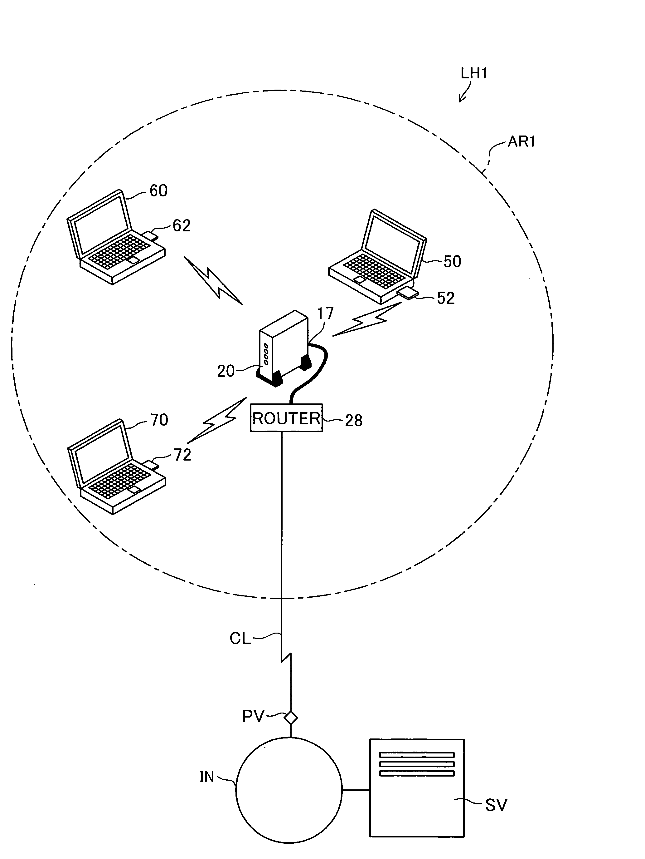
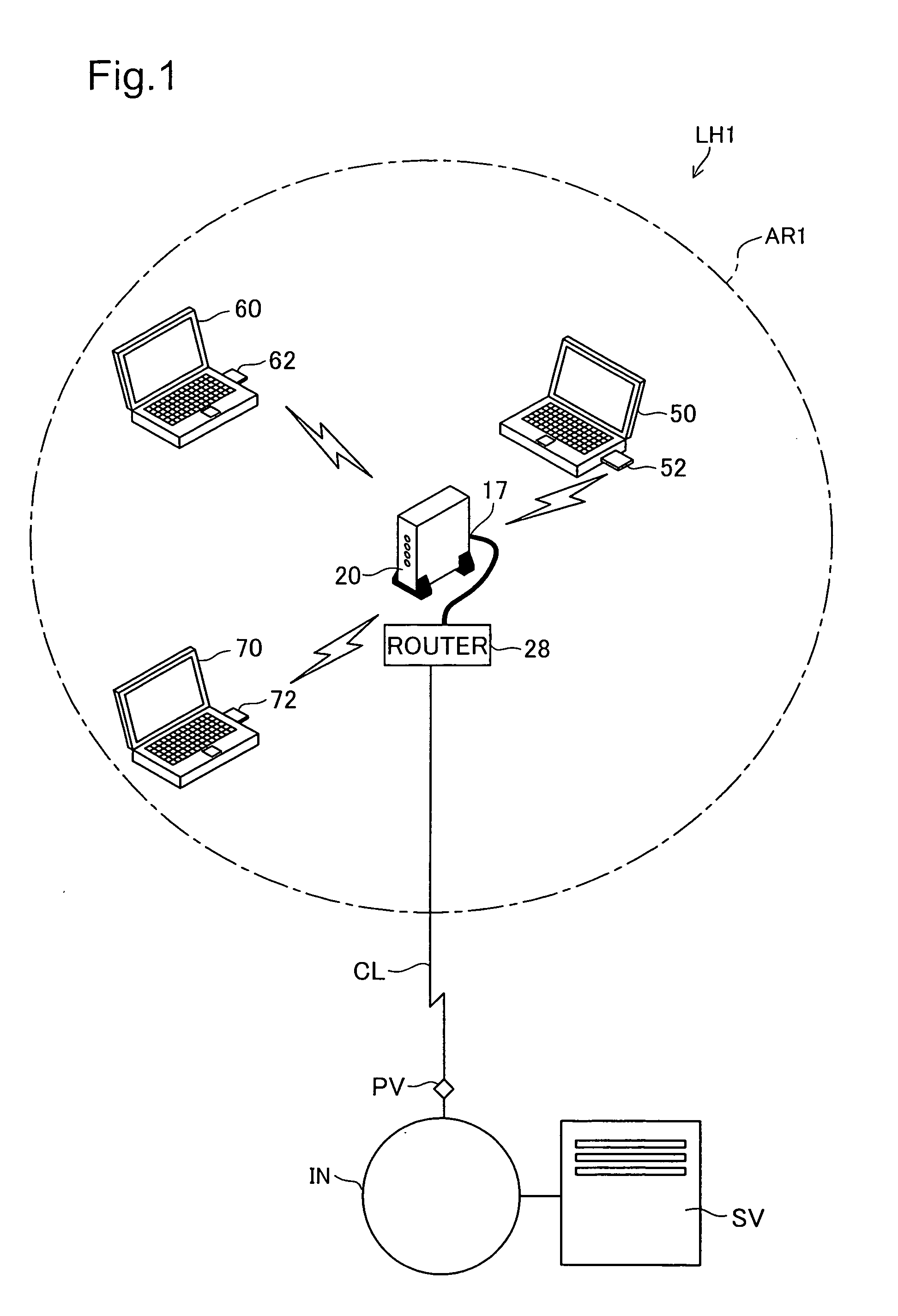
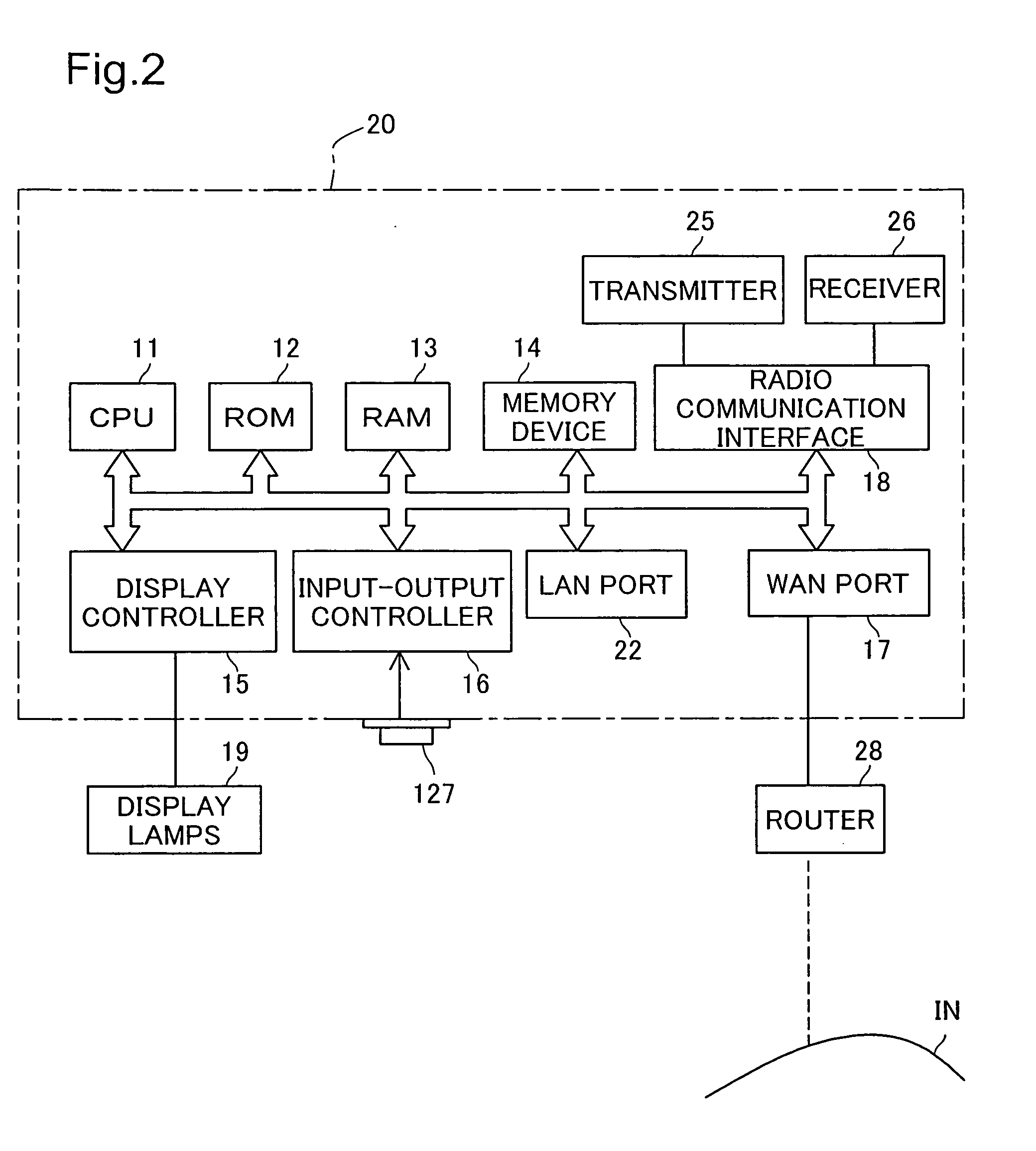
[0043]FIG. 1 is an explanatory diagram that shows the structure of hardware that realizes encryption key setting system LH1 which is a first working example of the present invention, and FIG. 2 is an explanatory diagram that shows the structure of access point 20. Encryption key setting system LH1 is a system that, by performing wireless communication between terminal 50 and access point 20 within wireless communication area AR1 of a wireless LAN with key data that represents the contents of the WEP key as the encryption key traveling on an electric wave, sets the WEP key that access point 20 uses for terminal 50.
[0044] As shown in FIG. 1, access point (wireless base station) 20 which is a relay for a wireless LAN is installed in wireless communication area AR1. As shown in FIG. 2, access point 20 comprises various parts such as CPU 11, ROM 12, RAM 13, non-volatile memory device such as a hard disk 14, WAN port 1...
PUM
 Abstract
Description
Claims
Application Information