Speaker

a technology for speakers and speakers, applied in the field of speakers, can solve the problems of difficult difficult to reduce speakers, and insufficient improvement of the distortion and quality of sound, so as to improve the performance of speakers, reduce the harmonizing distortion of speakers, and improve power linearity

Active Publication Date: 2005-09-15
PANASONIC CORP
View PDF8 Cites 38 Cited by
  • Summary
  • Abstract
  • Description
  • Claims
  • Application Information

AI Technical Summary

Benefits of technology

[0024] The suspension is formed using the first edge and second edge as discussed above, a damper causing the nonlinearity and asymmetry can be omitted. Additionally, the second edge is configured to cancel the asymmetry of the first edge, and hence the nonlinearity and asymmetry of the suspension can be essentially solved. Thus, the harmonic distortion of the speaker can be reduced, the power linearity can be improved, an

Problems solved by technology

This speaker therefore has problems related to the following items: linearity of relation between an input signal of the speaker and displacement of amplitude of diaphragm 5; symmetry in the vertical direction; and distortion and quality of sound.
In the speaker having the conventional configuration, however, the improvement

Method used


Image

  • Speaker
  • Speaker
  • Speaker

Examples


exemplary embodiment 1

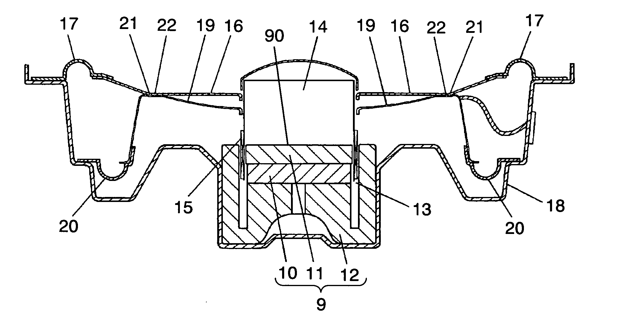
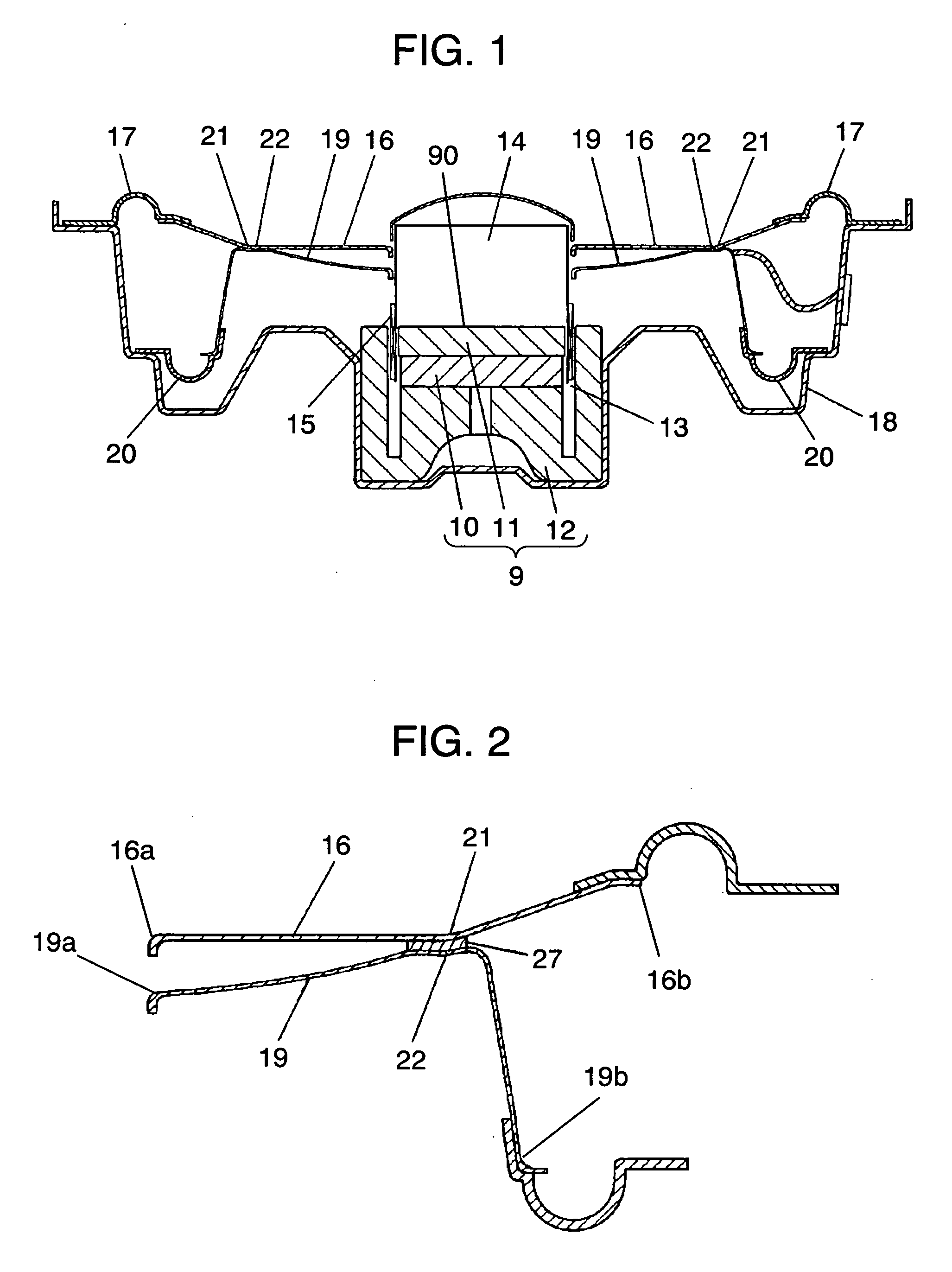
[0054]FIG. 1 is a sectional view of a speaker in accordance with exemplary embodiment 1 of the present invention. Magnetic circuit 9 has disk-like magnet 10, disk-like plate 11, and columnar yoke 12, and magnetic flux of magnet 10 is concentrated to magnetic gap 13 between the outer periphery of plate 11 and the inner periphery of yoke 12. Magnet 10 is mainly made of ferrite material or rare-earth cobalt material, and plate 11 and yoke 12 are mainly made of iron. Magnetic circuit 9 has top surface 90 and a bottom surface, the top surface corresponds to the upside surface of magnetic circuit 9 in FIG. 1, and the bottom surface corresponds to the downside surface of magnetic circuit 9. In FIG. 1, the bottom surface of magnetic circuit 9 is surrounded by frame 18. Cylindrical voice coil body 14 has coil section 15 movable in magnetic gap 13. Voice coil body 14 is configured so that coil section 15 is moved in magnetic gap 13 by a magnetic field of magnetic gap 13 when current is made t...

exemplary embodiment 2

[0086] A speaker in accordance with exemplary embodiment 2 of the present invention is described with reference to FIG. 8. The basic configuration of the speaker is similar to that of the speaker of embodiment 1 of the present invention, but projecting directions of first edge 17 and second edge 20 are different from those of the speaker of embodiment 1.

[0087] As shown in FIG. 8, first edge 17 is projected toward magnetic circuit 9, namely in the back direction of the diaphragm, and second edge 20 is projected in the front direction of the diaphragm.

[0088] Thus, even when an acoustic opening such as a net is close to the front side of first edge 17, contact of first edge 17 with the protective net can be prevented. Increasing amplitude margin of the speaker can therefore increase maximum sound pressure.

exemplary embodiment 3

[0089] A speaker in accordance with exemplary embodiment 3 of the present invention is described with reference to FIG. 9. The basic configuration of the speaker is similar to that of the speaker of embodiment 1 of the present invention, but the speaker of embodiment 3 differs from the speaker of embodiment 1 in that the outer periphery of suspension holder 19 is coupled through the second edge 20, on the bottom side of magnetic circuit 9, and below top surface 90 of plate 11.

[0090] Thanks to the configuration of FIG. 9, the distance between fulcrums of first edge 17 and second edge 20 can be made as long as possible, so that rolling of voice coil body 14 during moving can be minimized. In other words, the original position of voice coil body 14 during moving lies between the coupling point of first edge 17 with frame 18, namely the fulcrum of voice coil body 14, and the coupling point of second edge 20 with frame 18. The original position of voice coil body 14 indicates the coupli...


PUM


Abstract

A speaker has diaphragm (16) and suspension holder (19) disposed on the back surface of the diaphragm. In the diaphragm, the part from a bent section (21) disposed between the outer periphery and the inner periphery to the outer periphery is formed in a conical shape. The diaphragm is coupled to the suspension holder through the bent section of the diaphragm. This configuration can omit a damper causing the nonlinearity and asymmetry of suspension, reduce the harmonic distortion of the speaker, improve the power linearity, and improve the performance of the speaker. Even a flat shape can secure sufficient rigidity, so that securing the rigidity of the diaphragm does not require large thickness of the diaphragm and downsizing and low profile can be realized.

Description

TECHNICAL FIELD [0001] The present invention relates to a speaker used for various audio apparatuses. BACKGROUND ART [0002]FIG. 24 shows a conventional speaker. The conventional speaker has the following elements: [0003] magnetic circuit 1; [0004] voice coil body 4 having coil section 3 movable in magnetic gap 2; [0005] diaphragm 5 of which inner periphery is coupled to voice coil body 4 and outer periphery is coupled to frame 7 via edge 6; and [0006] damper 8 of which inner periphery is coupled to voice coil body 4 and outer periphery is coupled to frame 7. [0007] In the conventional speaker, when an electric signal output from an audio amplifier or the like is fed into coil section 3, voice coil body 4 vibrates, the vibromotive force is transmitted to diaphragm 5, and diaphragm 5 vibrates air to convert the electric signal to voice. Damper 8 is combined with edge 6 to form a suspension to prevent voice coil body 4 from rolling. Damper 8 has a combined shape of a plurality of corru...

Claims


Application Information

Patent Timeline
IPC IPC(8): H04R9/02H04R7/12H04R7/26H04R9/04H04R9/06
CPCH04R9/06H04R7/26H04R7/16H04R9/043
Inventor FUNAHASHI, OSAMUMORIMOTO, HIROYUKI
Owner PANASONIC CORP
Why Eureka
Try Eureka