Non-contact measurement method and apparatus

a measurement method and non-contact technology, applied in the field of three-dimensional space observation system, can solve the problems of time-consuming and laborious, affecting and the accuracy of the current cmm processing software, etc., to achieve the effect of reducing noise and increasing the accuracy and precision of data points

Inactive Publication Date: 2005-09-15
GENERAL ELECTRIC CO
View PDF18 Cites 47 Cited by
  • Summary
  • Abstract
  • Description
  • Claims
  • Application Information

AI Technical Summary

Benefits of technology

[0008] Briefly stated, the system of the present invention is directed to a non-contact imaging apparatus for examining a manufactured object having complex surfaces for shape deformations. The imaging apparatus includes at least one imaging device for obtaining a scanned image of surfaces of the manufactured object being examined. A predetermined reference model, or image of an ideal model for the manufactured object, is stored in a memory. An image register is coupled to the imaging device and to the memory containing reference image information for the ideal model. A transformation estimator compares the scanned image to the reference model and provides a transform by which the scanned image is mapped to the reference image to provide a set of registered object data points. One or more filters process the registered object data points with a priori information to reduce noise and to increase the accuracy and precision of the data points. The resulting information is passed to a gauge estimator which utilizes the processed and registered object data to identify gauge measurements for the manufactured object. The gauge measurements can be displayed to an operator, and utilized to control a manufacturing process by which the object is made.

Problems solved by technology

Traditionally, gauge measurement of a manufactured object having a complex three dimensional surface such as an airfoil (e.g. turbine blade) is a tedious and time consuming process.
However, the time to scan an airfoil is relatively slow because the sensor probe must be continually repositioned to obtain data.
Current CMM processing software, however, is also relatively slow.
It will be appreciated that hard gauging is costly since a new set of gauges must be machined for each object undergoing test, and they are inflexible to change.
Further, while hard gauging is fast, it does not provide dense measurement data, but rather provides only individual measurements at a relatively few defined contact points.
While the sensors are capable of scanning an object quickly and obtaining large quantities of data, the accuracy of this data is significantly lower than that obtained using CMMs.

Method used


Image

  • Non-contact measurement method and apparatus
  • Non-contact measurement method and apparatus
  • Non-contact measurement method and apparatus

Examples


Embodiment Construction

[0014] The following detailed description illustrates the invention by way of example and not by way of limitation. The description clearly enables one skilled in the art to make and use the invention, describes several embodiments, adaptations, variations, alternatives, and uses of the invention, including what is presently believed to be the best mode of carrying out the invention.

[0015] For purposes of this specification, the following definitions of terms are provided:

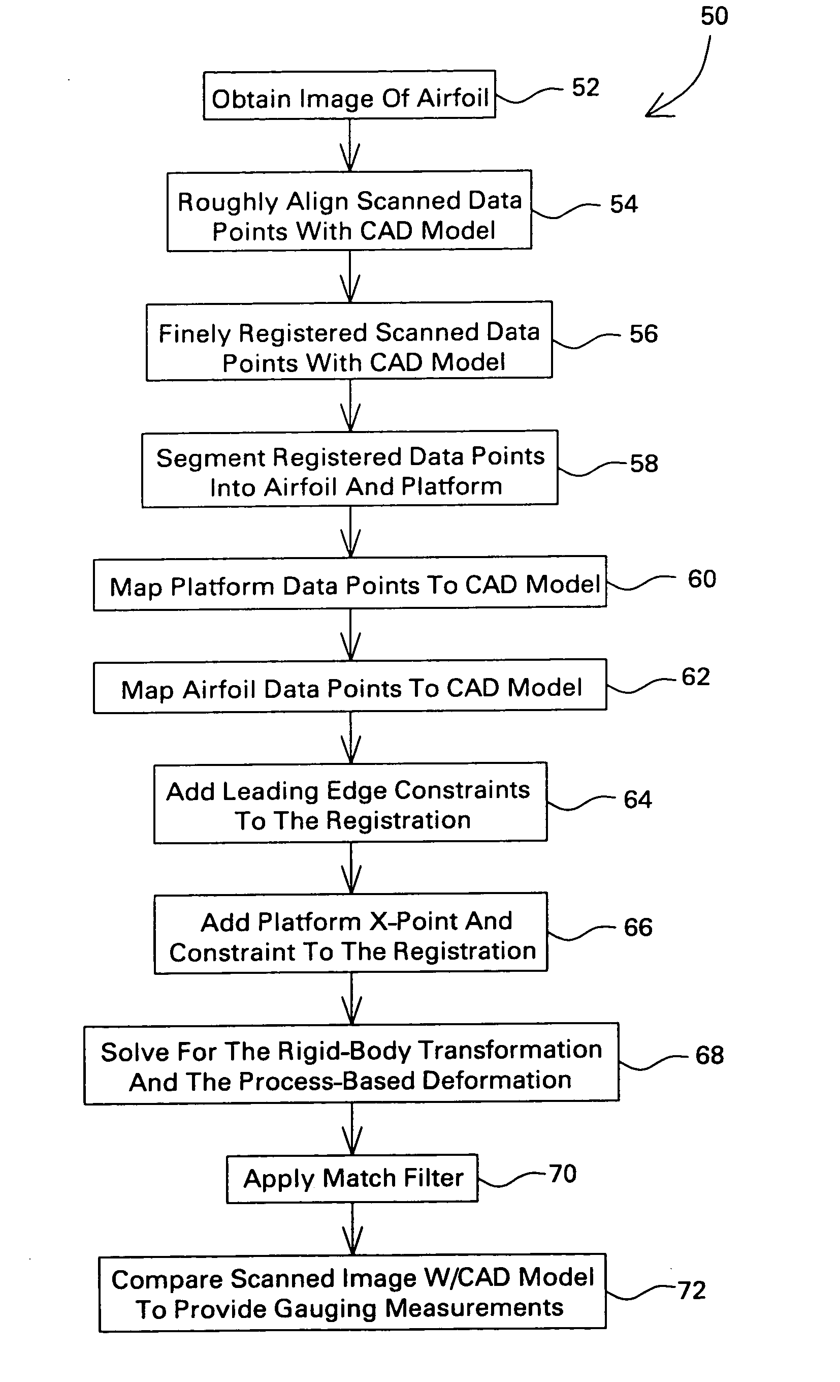
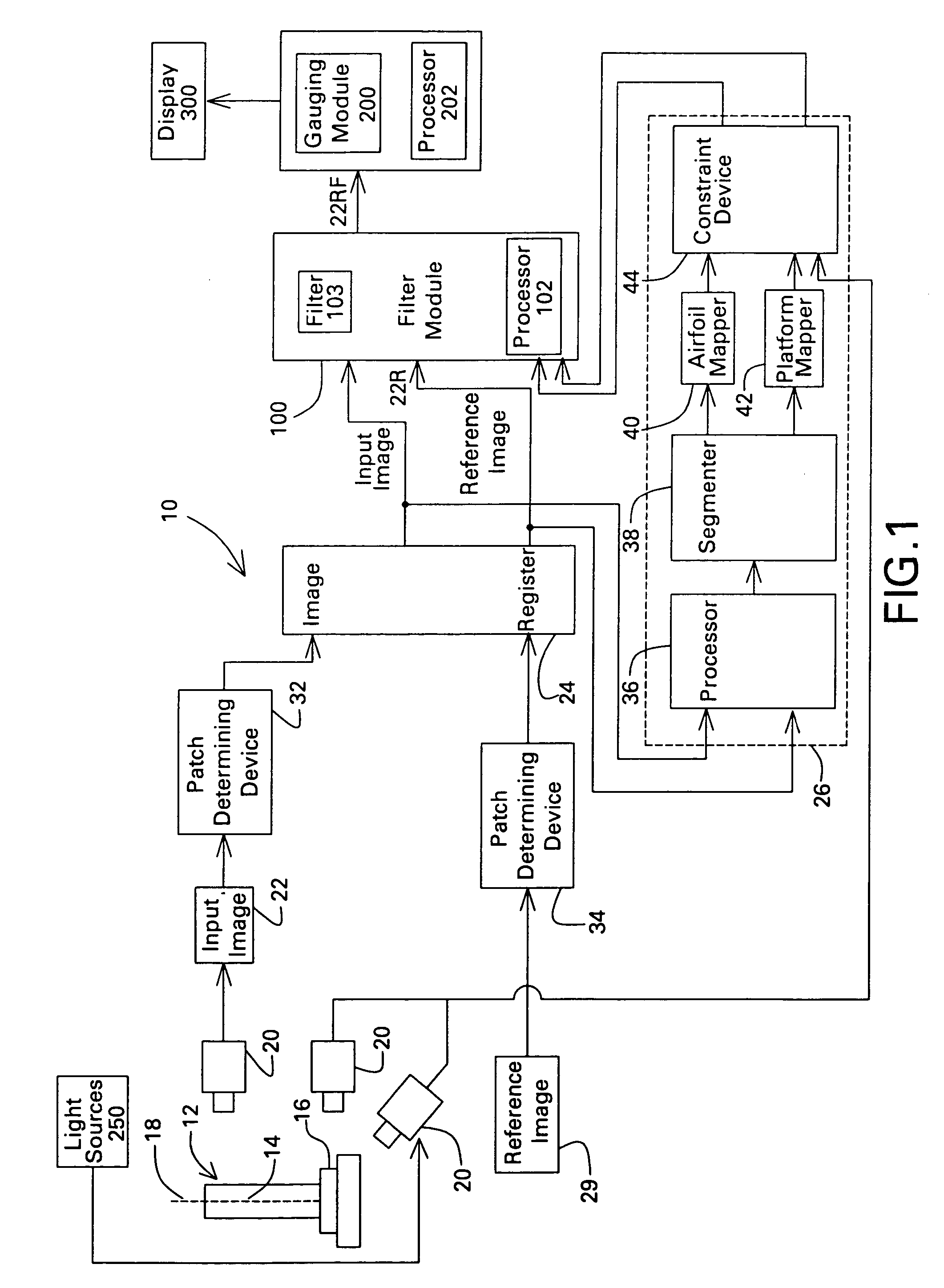
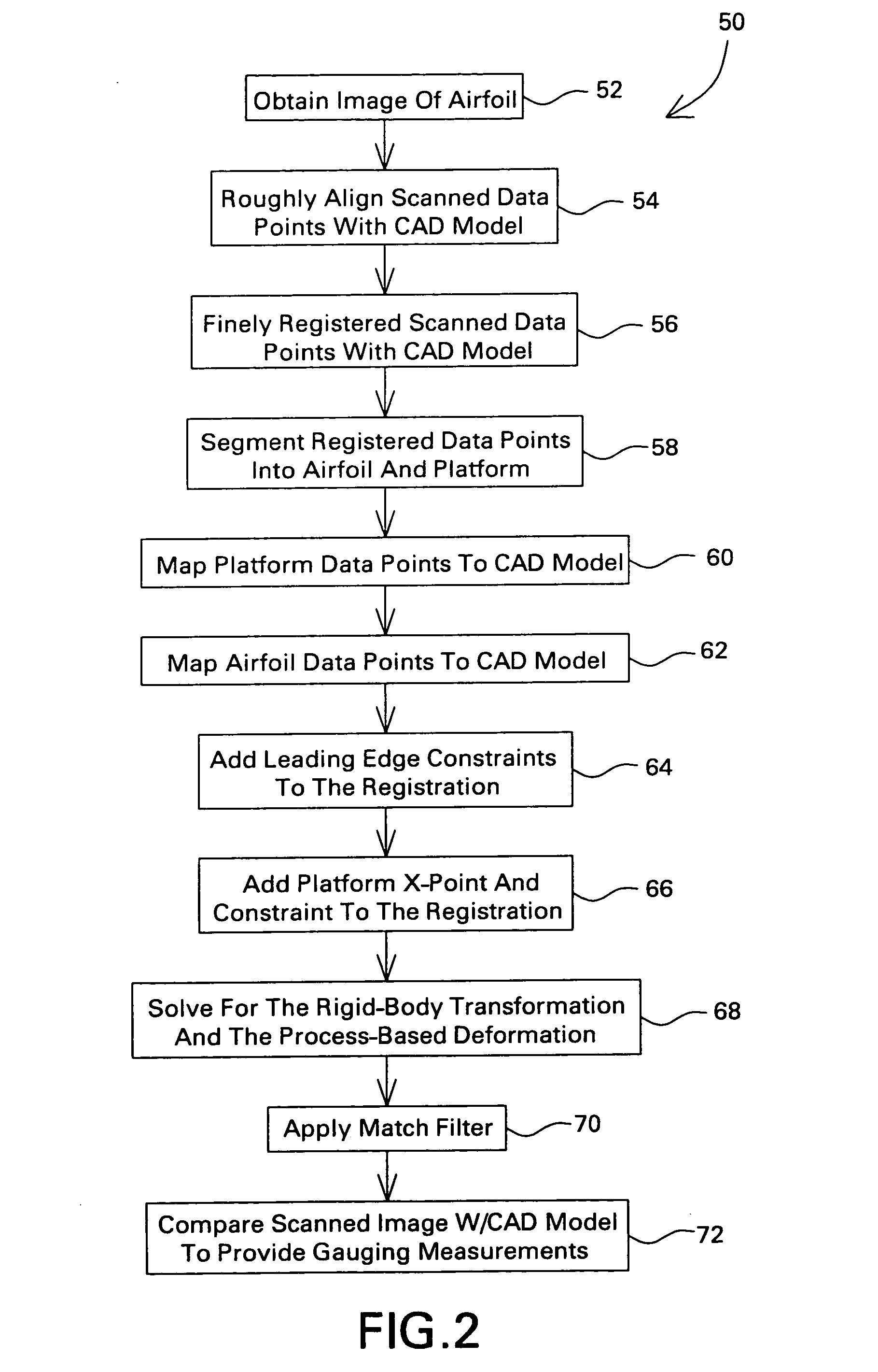
[0016] First, an “image” is defined as a collection of data representing properties, design specifications, or attributes of an object. For example, a data collection which represents the three spatial dimensions (X, Y, Z) of an object is an image of the object. When such data are obtained by measuring the object and storing the measurements in memory, the stored measured data is referred to herein as a “scanned image”.

[0017] Second, data comprising a CAD drawing, or other set of engineering specifications in di...


PUM


Abstract

A non-contact imaging apparatus for examining an object having complex surfaces or shape deformations. The imaging apparatus includes at least one imaging device for obtaining a scanned image of the exterior surfaces of the object being examined. A predetermined reference image) of an ideal model for the object is stored in a memory. An image register is coupled to the imaging device and to the memory containing the reference image of the ideal model for the object. A transformation estimator compares the scanned image to the reference image and provides a transform which maps the scanned image to the reference image and provides a set of registered object data points. One or more filter modules process the registered object data points with a priori information to reduce noise and to further enhance the accuracy and precision of the registration. A gauge estimator is coupled to the filter module. The gauge estimator utilizes the processed and registered object data to determine deformation parameters of the object, which are then displayed to an operator as gauging information.

Description

STATEMENT REGARDING FEDERALLY SPONSORED RESEARCH [0001] The US Government may have certain rights in this invention pursuant to contract number 70NANB5H1085 awarded by the National Institute of Standards and Technology (NIST).BACKGROUND OF THE INVENTION [0002] The present invention relates to a system for observing objects in three-dimensional space. More particularly, the invention relates to a multi-camera, three dimensional sensing system for observing an object by disambiguating reflections of multiple light patterns from a sensed object to obtain a set of data points defining the three dimensional shape of the object. This set of data points is then compared with a set of predetermined ideal shape information data points, or a reference model, to identify gauge measurements of the object. [0003] Traditionally, gauge measurement of a manufactured object having a complex three dimensional surface such as an airfoil (e.g. turbine blade) is a tedious and time consuming process. Air...

Claims


Application Information

Patent Timeline
Patent Type & Authority Applications(United States)
IPC IPC(8): F01D5/14G01B11/00F01D21/00G01B11/24G01B11/25G06T1/00G06T5/00
CPCF01D5/141Y02T50/673G01B11/2522F01D21/003Y02T50/60
Inventor LLOYD, THOMAS WATKINS JR.ROSS, JOSEPH BENJAMINBROOKSBY, GLEN WILLIAMNGUYEN, VAN-DUCSCHNEITER, JOHN LEWISGORDON, STEVEN JEFFREYBENAYAD-CHERIF, FAYCALNZOMIGNI, VICTORHAMILTON, DONALD
Owner GENERAL ELECTRIC CO
Why Eureka
Try Eureka