Electromagnetic control of chemical catalysis

a technology of electromagnetism and chemical catalysis, which is applied in the direction of solid-state diffusion coating, chemical/physical/physical-chemical processes, coatings, etc., can solve the problems of rapid cooling of metallic structures, the proximity of catalysts and/or heat applied, and the difficulty of having control of catalyst temperature, so as to achieve fast cooling of metallic structures and dissipate more quickly

Active Publication Date: 2005-09-15
CALIFORNIA INST OF TECH
View PDF14 Cites 26 Cited by
  • Summary
  • Abstract
  • Description
  • Claims
  • Application Information

AI Technical Summary

Benefits of technology

[0028] Controlling the electromagnetic radiation source can be used to at least turn on / off heating. Heating is induced more rapidly and dissipates more rapidly since it is the interaction of incident electromagnetic radiation with the metallic nanostructures that establishes, via at least Photon-Electron resonance, localized heating of the metallic structures and not the whole of the substrate. Removing the incident electromagnetic radiation flux, having the appropriate frequency or range of frequencies, from the metallic structures results in very fast cooling of the metallic structures due to the small size / mass of the metallic structures.

Problems solved by technology

Inherent with the use of such conventional methods of heating, is the difficulty of having control of the temperature of a catalyst, the vicinity of the catalyst and / or the heat applied, both temporally and spatially.
Stopping incident electromagnetic radiation flux to the nanometer sized structures results in very rapid lowering of temperature at the nanometer sized structures, i.e. a previously established Photon-Electron resonance of these structures attenuates / diminishes, as does the associated generated localized heat.
Removing the incident electromagnetic radiation flux, having the appropriate frequency or range of frequencies, from the metallic structures results in very fast cooling of the metallic structures due to the small size / mass of the metallic structures.

Method used


Image

  • Electromagnetic control of chemical catalysis
  • Electromagnetic control of chemical catalysis
  • Electromagnetic control of chemical catalysis

Examples


Embodiment Construction

[0059] Descriptions of exemplary implementations are provided and reference made to the accompanying figures which form the part thereof, and which are shown by way of illustration of exemplary implementation of teachings provided herein. It is to be understood that other implementations and application of the teachings provided herein may be utilized and structural and functional changes may be made without departing from the spirit and scope of the present disclosure. Additionally, the figures are for illustrative purposes and no relative or limiting sizes, scales or ratios are intended.

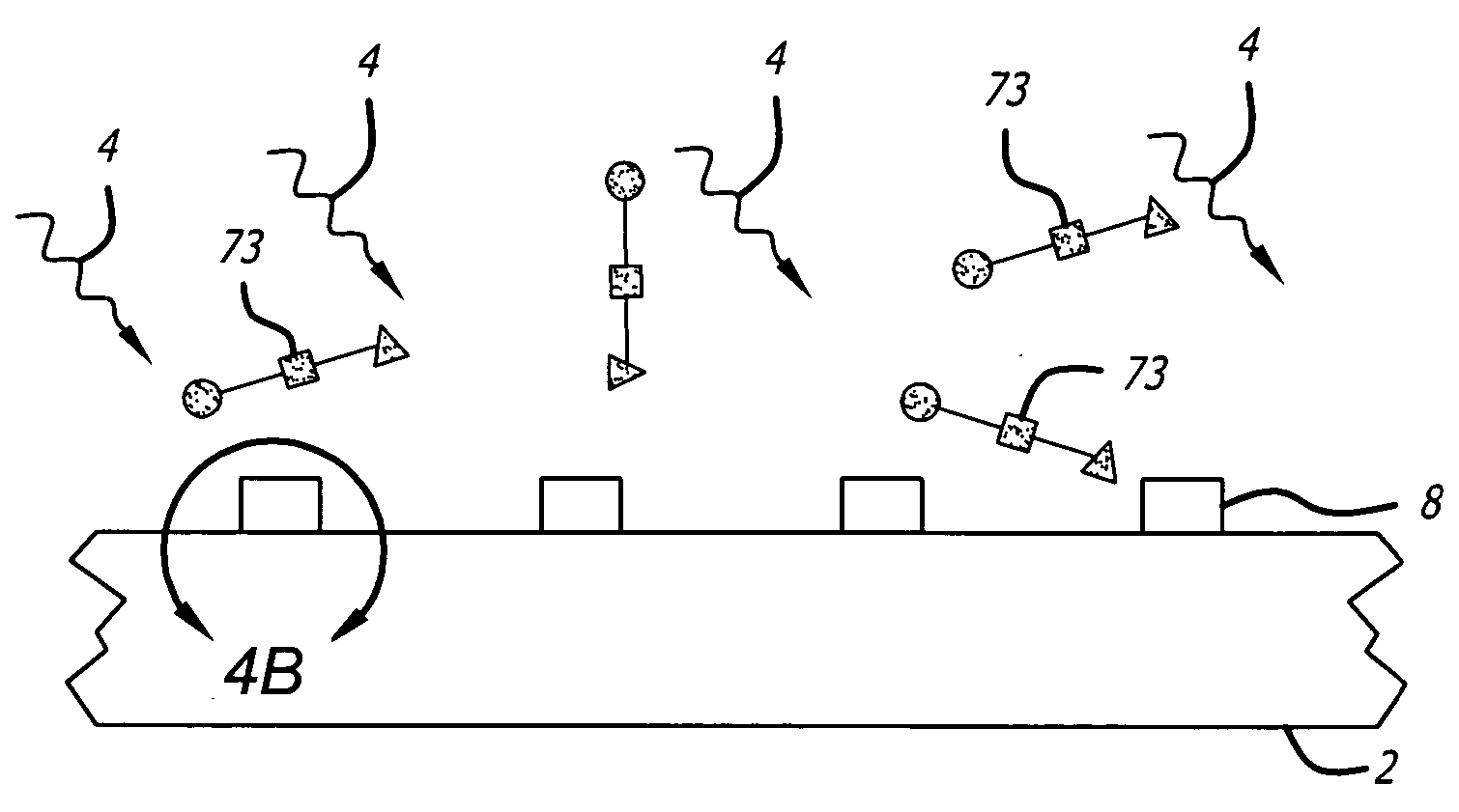
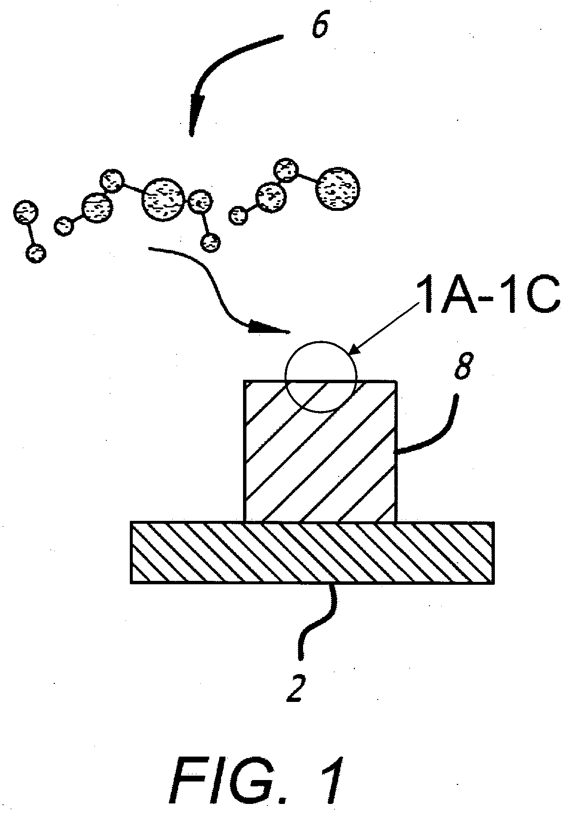
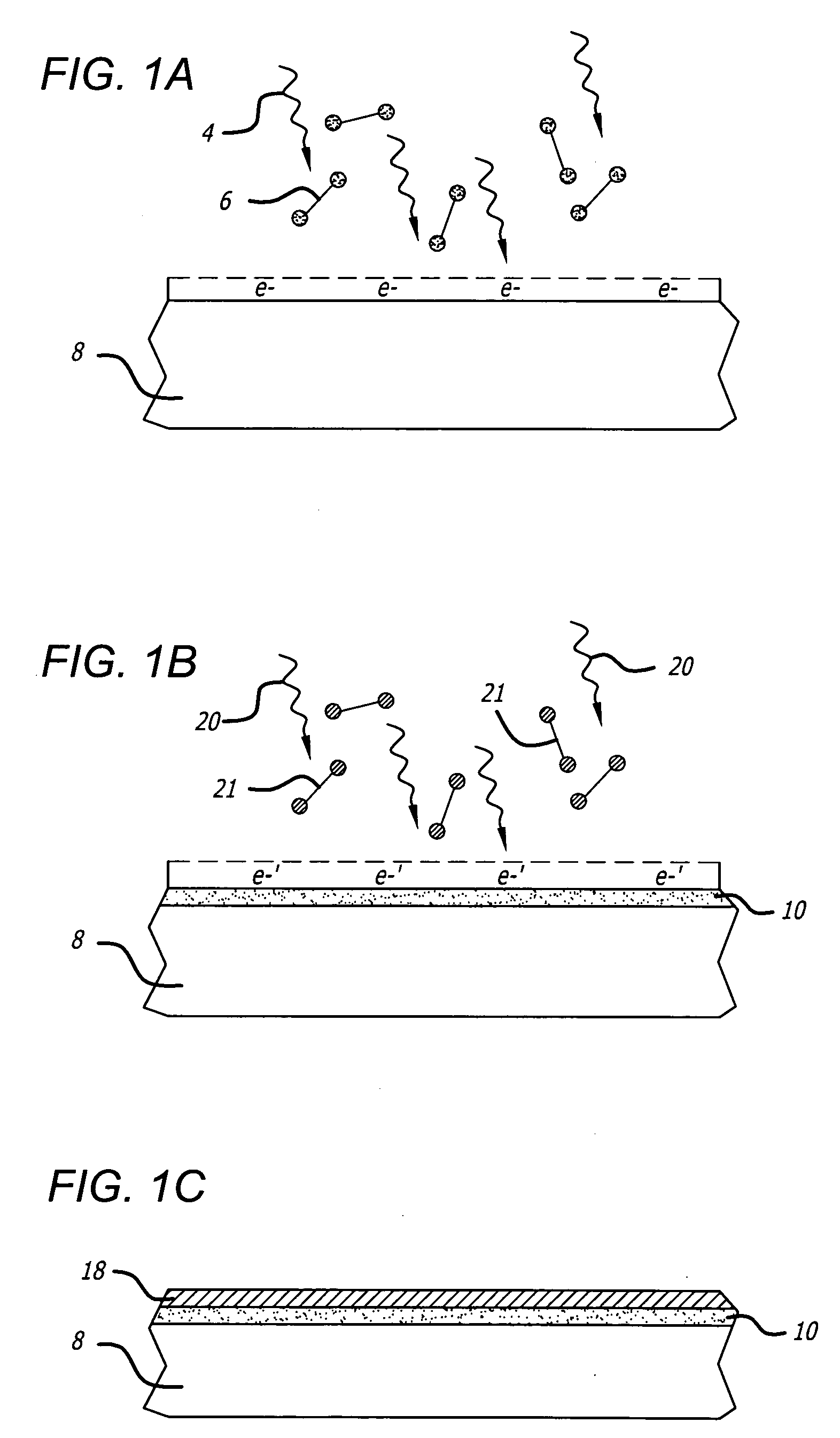
[0060] Techniques directed to micro or nanostructures and their applications are provided. More particularly and in one aspect, the teachings disclosed herein provide methods, systems and resulting structures and their use for forming nano and micro structures using novel deposition techniques useful for a wide variety of applications. As merely an example, such deposition techniques can be applie...


PUM

PropertyMeasurementUnit
diameteraaaaaaaaaa
diameteraaaaaaaaaa
radiusaaaaaaaaaa

Abstract

The present disclosure methods and systems that provide heat, via at least Photon-Electron resonance, also known as excitation, of at least a particle utilized, at least in part, to initiate and/or drive at least one catalytic chemical reaction. In some implementations, the particles are structures or metallic structures, such as nanostructures. The one or more metallic structures are heat at least as a result of interaction of incident electromagnetic radiation, having particular frequencies and/or frequency ranges, with delocalized surface electrons of the one or more particles. This provides a control of catalytic chemical reactions, via spatial and temporal control of generated heat, on the scale of nanometers as well as a method by which catalytic chemical reaction temperatures are provided.

Description

RELATED APPLICATIONS [0001] This application claims benefit of and priority to U.S. Provisional Patent Application No. 60 / 529,869, filed Dec. 15, 2003 entitled “Process of Chemical Vapor Deposition of Arrayed Nanostructures: Photon-Electron Assisted CVD”, herein incorporated by reference in its entirety.BACKGROUND [0002] 1. Field [0003] The present disclosure is directed to localized heating of micro or nanostructures and their associated methods of use and applications. More particularly and in one aspect, the teachings disclosed herein also provides very localized heating of specific nano and micro structures for the purpose of influencing a catalyzed chemical reaction. In one aspect providing heat for a chemical reaction that takes place on and / or adjacent to a provided structure or plurality thereof which generate heat as a result of at least a Photon-Electron resonance, as taught herein. [0004] 2. Related Art [0005] The use of catalysis in large-scale, continuous chemical proce...

Claims


Application Information

Patent Timeline
Patent Type & Authority Applications(United States)
IPC IPC(8): C23C8/00C23C16/00
CPCC23C16/00C23C8/00B82Y30/00B01J2219/0892B01J19/127
Inventor GREENGARD, LESLIE FREDERICKBRONGERSMA, MARKBOYD, DAVID A.
Owner CALIFORNIA INST OF TECH
Why Eureka
Try Eureka