Shutter mechanism for fuel cell

a technology of fuel cell and shutter mechanism, which is applied in the direction of fuel cell, solid electrolyte fuel cell, electrical apparatus, etc., can solve the problems of limiting the performance of the fuel cell, reducing the efficiency of the system, and limiting the efficiency of the reformer based system

Inactive Publication Date: 2005-09-15
MTI MICROFUEL CELLS
View PDF15 Cites 25 Cited by
  • Summary
  • Abstract
  • Description
  • Claims
  • Application Information

AI Technical Summary

Benefits of technology

[0017] The present invention provides a shutter assembly for use with a direct oxidation fuel cell system. On the anode side, the shutter mechanism includes a moving shutter plate that is disposed between a reactant and the MEA. For example, on the anode side, the moving shutter plate is disposed between the fuel source and the anode aspect of the membrane electrolyte, and preferably between the passive mass transport barrier, if any, and the anode current collector. One embodiment of the shutter mechanism of the present invention operates in a z-axis plane perpendicular to the plate itself and in the general direction of fuel flow. In this manner, additional lateral volume is not required for movement of the shutter plate.

Problems solved by technology

However, because fuel processing is complex and generally requires components which occupy significant volume, reformer based systems are presently limited to comparatively large, high power applications.
This reaction is normally not desirable as it leads to wasting fuel and decreasing the efficiency of the system.
In addition, excess water could result in cathode flooding, which inhibits the introduction of oxygen to the cathode aspect of the fuel cell, thus limiting performance of the fuel cell.
Furthermore, excess heat can result in lower performance of the fuel cell and possible deterioration of some fuel cell component structures.
Some known shutter mechanisms, such as those described above, can require additional volume to accommodate the open-and-close cycle of movement of the mechanism, which results in the shutter components and mechanism adding unwanted volume, price and complexity to the fuel cell system.

Method used


Image

  • Shutter mechanism for fuel cell
  • Shutter mechanism for fuel cell
  • Shutter mechanism for fuel cell

Examples


Embodiment Construction

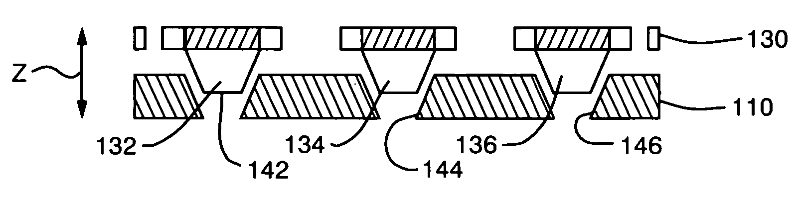
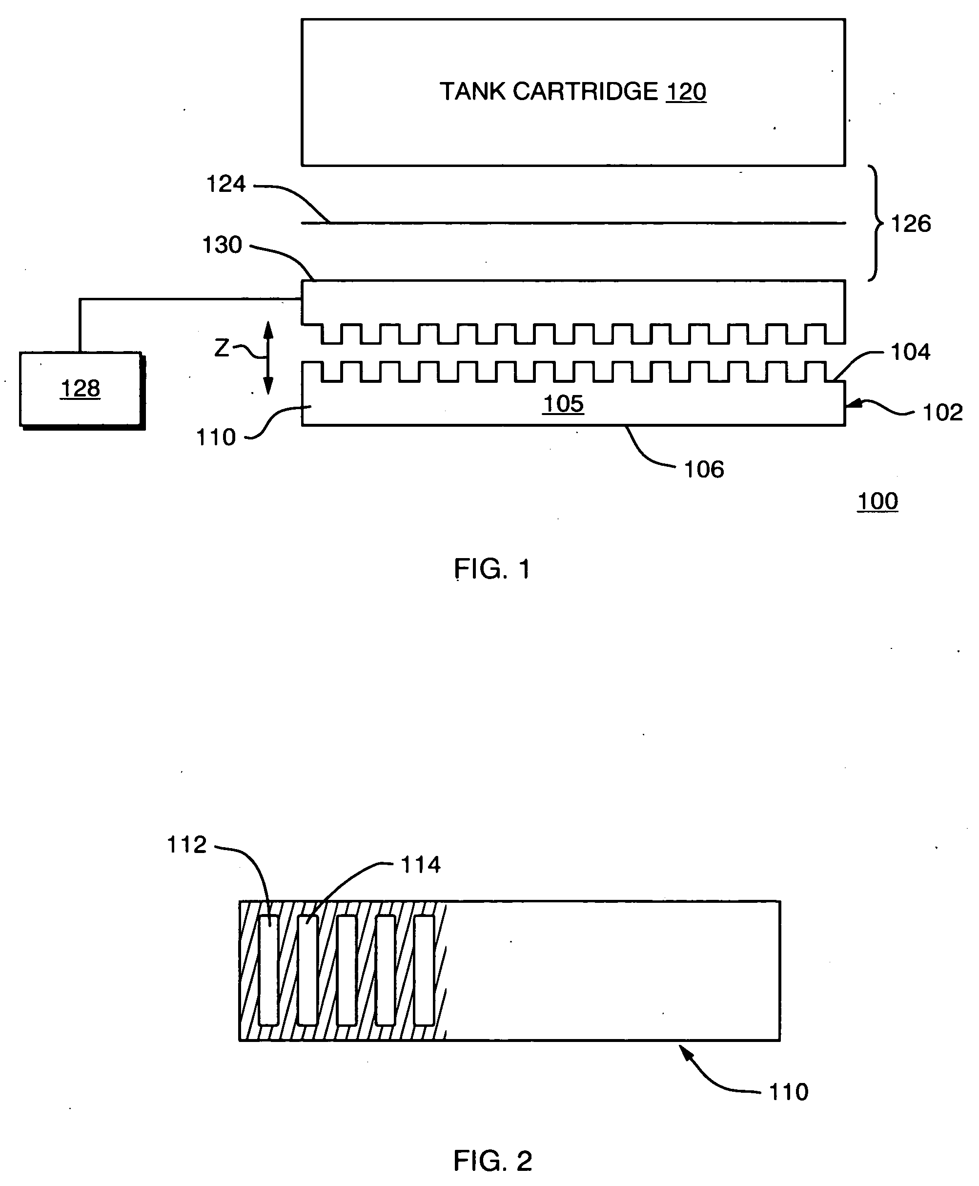
[0035]FIG. 1 illustrates a portion of a fuel cell system 100, which includes a fuel cell 102 that has a membrane electrode assembly fabricated using methods and materials known to those skilled in the art. Although not shown separately in FIG. 1, a membrane electrode assembly includes a protonically-conductive membrane such as NAFION®, which is commercially available from E.I. DuPont de Nemours and Company of Delaware, United States of America. A catalyst is disposed on or in close proximity, and preferably in intimate contact with each of the major surfaces of the membrane thus forming a catalyzed membrane electrolyte. The catalyzed membrane electrolyte has a catalyzed anode aspect and a catalyzed cathode aspect. Diffusion layers may also be included. Current collectors, typically comprised of an open conductive structure, as described herein, are used to conduct and collect electrons through an external load.

[0036] Fuel is delivered from an associated fuel source or cartridge 120...


PUM

PropertyMeasurementUnit
protonically conductiveaaaaaaaaaa
mass transportaaaaaaaaaa
volumeaaaaaaaaaa

Abstract

A shutter mechanism for use with a direct oxidation fuel cell system is provided within a fuel cell system between the reactant to be controlled and the MEA of the fuel cell. On the anode side, the shutter mechanism can disposed in the vapor gap between a passive mass transport barrier and the anode current collector. This embodiment of the shutter mechanism of the present invention operates in z-axis plane perpendicular to the plate itself and perpendicular to the general direction of fuel flow. In this manner, additional lateral volume is not required for movement of the shutter plate. In accordance with another aspect of the invention, one part of the shutter mechanism is integrated into the current collector, the fuel cell housing, or other component of the fuel cell. In other words, the moving shutter plate has features that correspond with openings in either the anode or the cathode current collector, and such features can be used in conjunction with the current collector to provide control of substances travelling into and out of the fuel cell. The present invention can also be used for heat transfer within the fuel cell system.

Description

BACKGROUND OF THE INVENTION [0001] 1. Field of the Invention [0002] This invention relates generally to direct oxidation fuel cells, and more particularly, to controlling fuel delivery and other substances within a fuel cell system. [0003] 2. Background Information [0004] Fuel cells are devices in which an electrochemical reaction involving a fuel molecule is used to generate electricity. A variety of compounds may be suited for use as a fuel depending upon the specific nature of the cell. Organic compounds, such as methanol or natural gas, are attractive fuel choices due to the their high specific energy. [0005] Fuel cell systems may be divided into “reformer-based” systems (i.e., those in which the fuel is processed in some fashion to extract hydrogen from the fuel before it is introduced into the fuel cell system) or “direct oxidation” systems in which the fuel is fed directly into the cell without the need for separate internal or external processing. Many currently developed fu...

Claims


Application Information

Patent Timeline
Patent Type & Authority Applications(United States)
IPC IPC(8): H01M8/04
CPCH01M8/04186Y02E60/523H01M8/1011H01M8/04753Y02E60/50
Inventor SCHWEIZER, PATRICK M.
Owner MTI MICROFUEL CELLS
Why Eureka
Try Eureka