
Eureka
For R&D, Eureka makes reading and utilizing patents & technical documents easy.
Eureka AIR
Designed for self-driven R&D workflows. Generate viable solutions, solve complex R&D challenges, empower your innovation with AI.

Eureka Materials
Designed for material experts only. Revolutionize your material R&D, from search, analyze, to developing new materials.

TechResearch
Generate reliable direction feasibility study reports for your R&D in just a few steps.

TechSeek
Discover and master advanced knowledge NOW. Basics, ideas, possibilities, all at once.

TechMind
As an expert in R&D Theories, TechMind can generates customized viable solutions instantly.

TechRisk
Analyze your overall solution with one click, know your potential R&D risks in advance.

TechMonitor
Get weekly tech updates, stay abreast of the latest tech innovations and key insights.
Transmitter and transceiver
- Summary
- Abstract
- Description
- Claims
- Application Information
AI Technical Summary
Benefits of technology
Problems solved by technology
Method used
Image

Examples
embodiment 1
[0046] Embodiment 1 of the invention is described below with reference to the drawings.
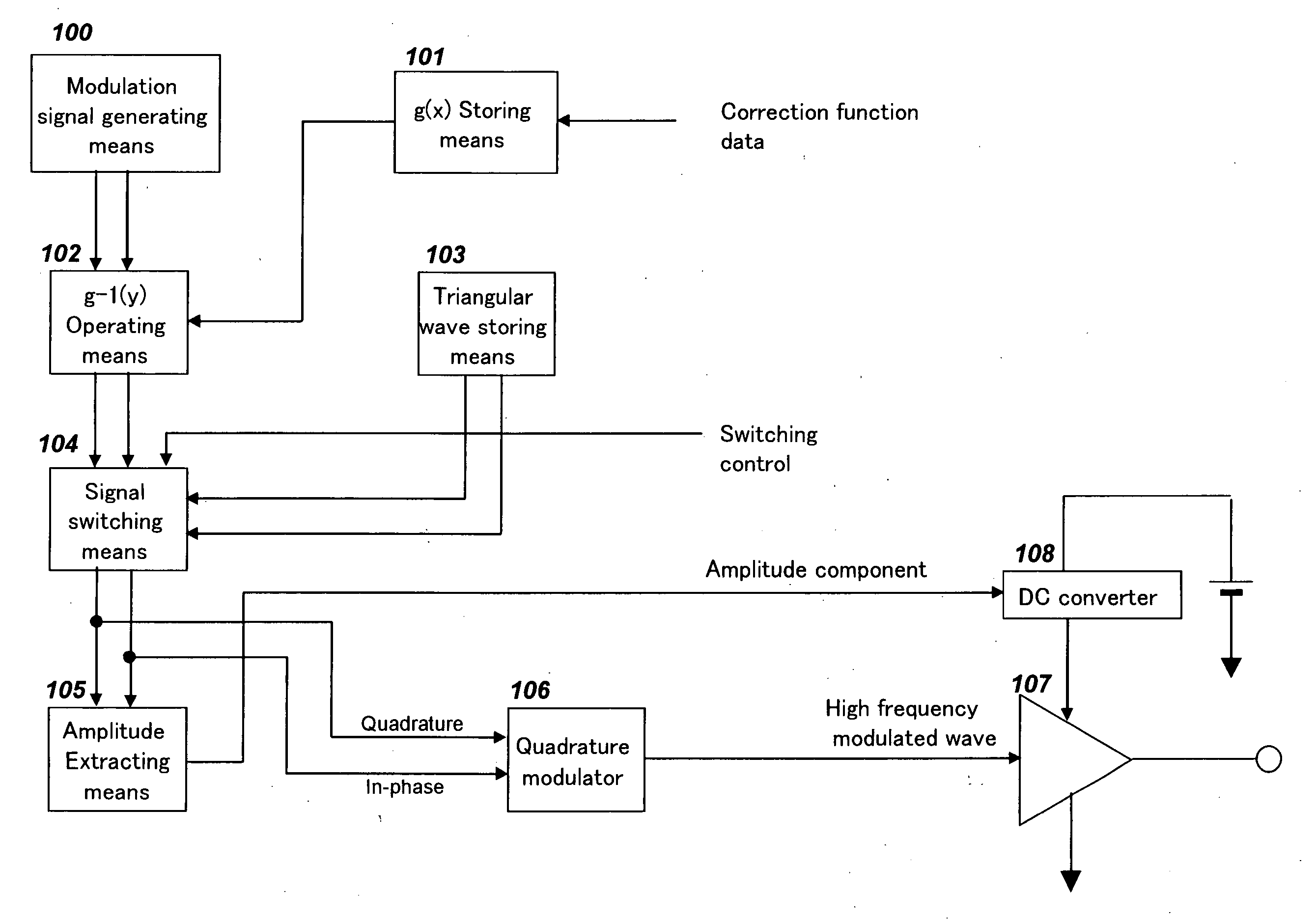
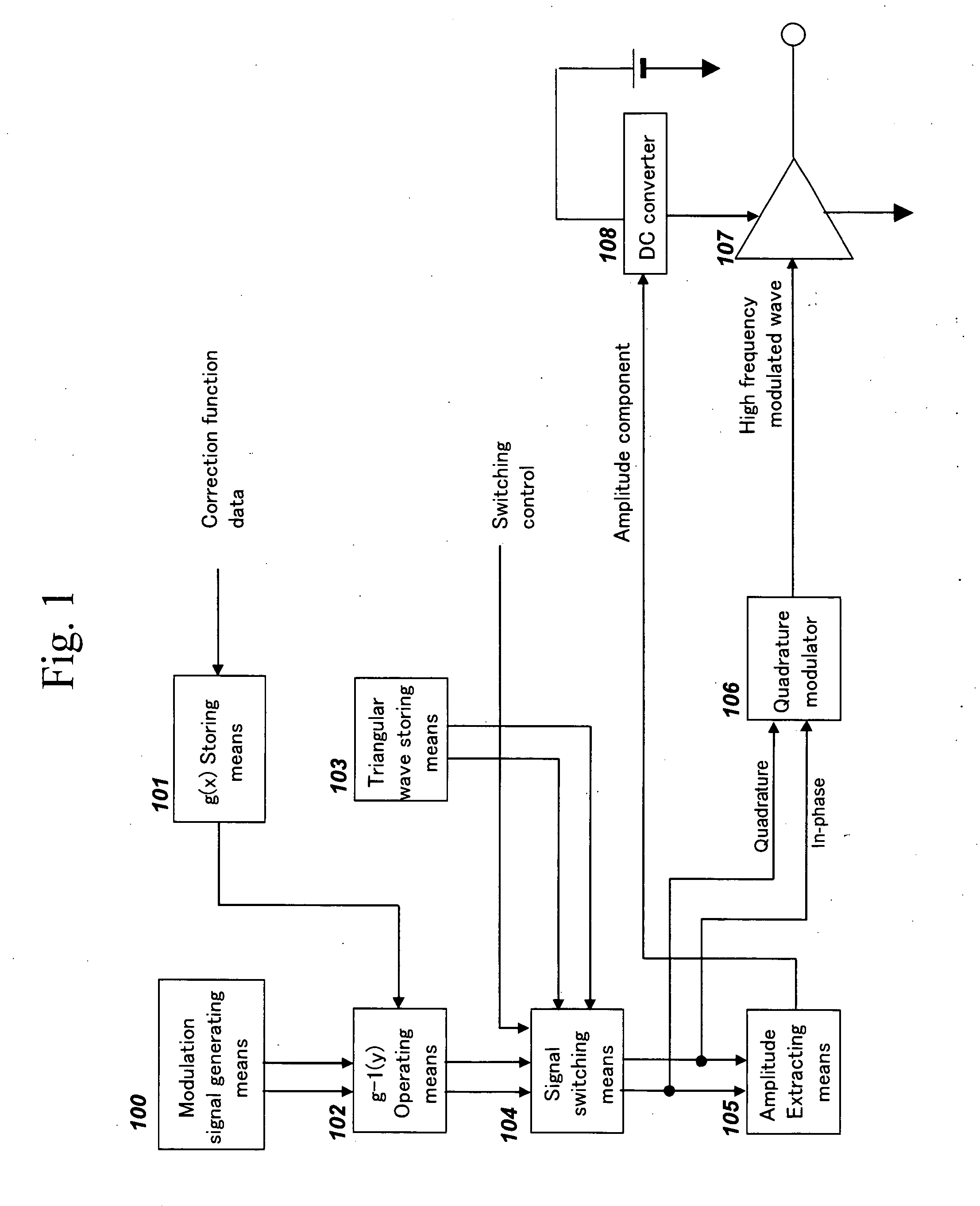
[0047]FIG. 1 is a circuit diagram of a transmitter capable of achieving a precise EER method according to Embodiment 1 of the invention. As shown in FIG. 1, the transmitter comprises, modulation signal generating means 100, g(x) storing means 101, g−1(y) operating means 102, triangular wave storing means 103, signal switching means 104, amplitude extracting means 105, a quadrature modulator 106, a high frequency power amplifier 107, and a DC converter 108.
[0048] The g(x) storing means 101 stores written-in data of a correction function y=g(x) generated by converting in to a complex voltage vector y the result of response of the output power to the input power of the high frequency power amplifier 107 when a voltage x is provided to the drain or the collector power supply terminal of the high frequency power amplifier 107 composed of a field-effect transistor, a bipolar transistor, or the like, a...
embodiment 2
[0081] Embodiment 2 of the invention is described below with reference to the drawings.
[0082]FIG. 3 is a circuit diagram of a transceiver capable of performing a precise EER method according to Embodiment 2 of the invention. This embodiment employs the above-mentioned configuration of a transmitter according to Embodiment 1. Thus, the functional operation of the transmitter part is the same as described above, and hence its description is omitted here. Further, like components are designated by like numerals.
[0083] Newly added components are a transmission / reception selector switch 300, an antenna 301, a low noise amplifier 302, a quadrature demodulator 303, signal switching means 304, and averaging calculation means 305.
[0084] The operation in the present embodiment is described below.
[0085] This configuration is expected to employ a time domain duplex (TDD) transceiver. As described above in Embodiment 1, when the transmitter performs distortion compensation for the high frequ...
embodiment 3
[0096] Embodiment 3 of the invention is described below with reference to the drawings.
[0097]FIG. 4 is a diagram of a circuit capable of performing a precise EER method using a high frequency power amplifier according to Embodiment 3 of the invention. Like components to Embodiment 1 shown in FIG. 1 are designated by like numerals. In the present embodiment, triangular wave storing means 103 and an interface 400 are built into a high frequency power amplifier 107. The triangular wave storing means 103 built into the high frequency power amplifier 107 outputs a triangular wave signal through the interface 400 to the signal switching means 104. In FIG. 4, numeral 107A indicates the power amplification section which is the main part of the high frequency power amplifier 107. The quadrature modulator 106 is composed of a reference oscillator 106A and a mixer 106B.
[0098] This embodiment is effective, for example, in the case that a baseband LSI provided with modulation signal generating...
PUM
 Abstract
Description
Claims
Application Information
 - R&D Engineer
- R&D Manager
- IP Professional
- Industry Leading Data Capabilities
- Powerful AI technology
- Patent DNA Extraction
Browse by: Latest US Patents, China's latest patents, Technical Efficacy Thesaurus, Application Domain, Technology Topic, Popular Technical Reports.
© 2024 PatSnap. All rights reserved.Legal|Privacy policy|Modern Slavery Act Transparency Statement|Sitemap|About US| Contact US: help@patsnap.com