Endoscope with fiber optic transmission of digital video

a fiber optic transmission and endoscope technology, applied in the field of imaging endoscopes, can solve problems such as potential electrical safety risks

Inactive Publication Date: 2005-09-15
SCI MED LIFE SYST
View PDF7 Cites 95 Cited by
  • Summary
  • Abstract
  • Description
  • Claims
  • Application Information

AI Technical Summary

Benefits of technology

[0007] The present invention is directed to a video endoscope in which the imaging chip at the distal tip communicates with the proximal connector and operator console by means of electrical signals impressed on an optical fiber. Electronic video data are encoded upon the optical fiber by a pulse-code modulator (PCM) circuit and light emitter with lensing. In one embodiment, the video data are digital. A small, inexpensive, flexible optical fiber in the endoscope body thus conveys the PCM optical data to a receiving circuit, preferably via an optical connector at the proximal end of the endoscope, or by a proximal optical-to-electronic video chip and electrical connector, and to decoding and display circuits in the operator console. It will be appreciated that fiber optic transmission overcomes the difficulty of electrical transmission of wide band digital video signals via miniature cables, which can be expensive, bulky, inflexible, susceptible to noise and interference, and constitute a potential electrical safety risk by leakage currents.

Problems solved by technology

It will be appreciated that fiber optic transmission overcomes the difficulty of electrical transmission of wide band digital video signals via miniature cables, which can be expensive, bulky, inflexible, susceptible to noise and interference, and constitute a potential electrical safety risk by leakage currents.

Method used


Image

  • Endoscope with fiber optic transmission of digital video
  • Endoscope with fiber optic transmission of digital video
  • Endoscope with fiber optic transmission of digital video

Examples


Embodiment Construction

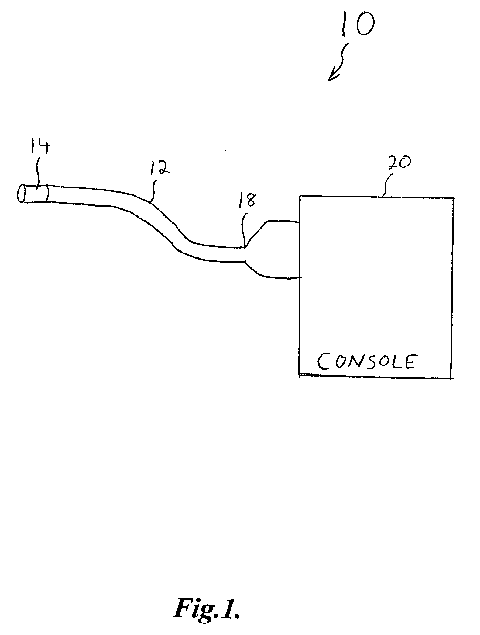
[0013]FIG. 1 is a diagram of an endoscope system 10 that is formed in accordance with the present invention. The endoscope system 10 includes a flexible catheter body 12 having a distal end 14. The catheter body 12 also includes a proximal end 18 which is coupled to a console 20. The console 20 provides electrical connections for the catheter body, such that the image signals can be received and processed, as will be described in more detail below.

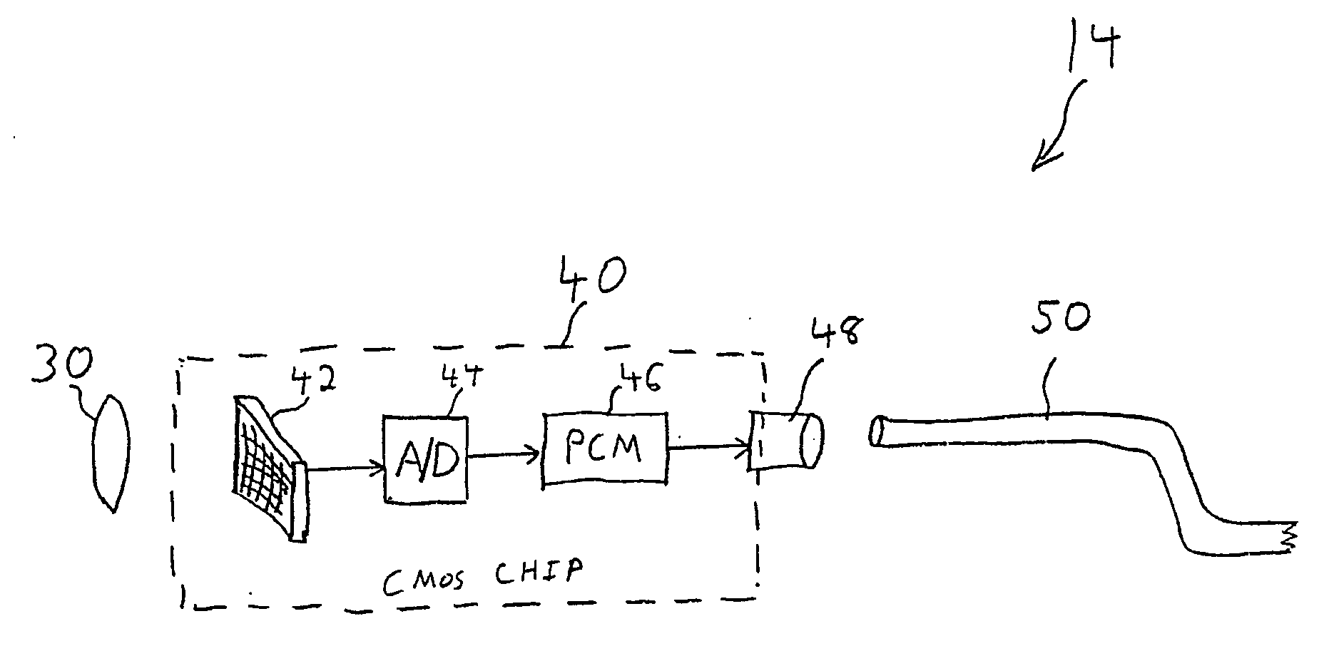
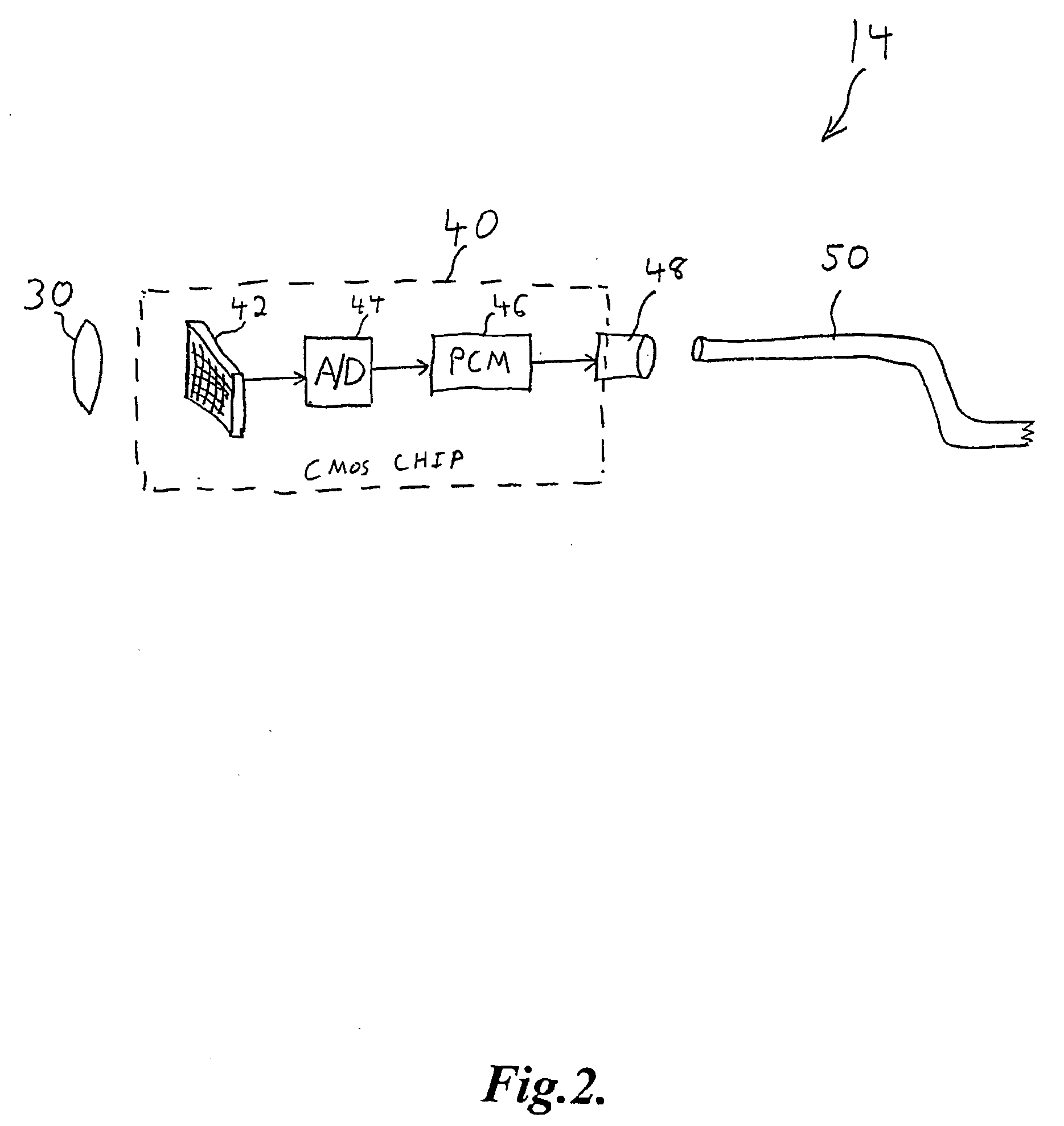
[0014]FIG. 2 shows the components of the distal tip 14 of the endoscope system 10. The distal tip 14 includes an optical lens 30, a CMOS chip 40, a photo diode 48, and a transmission fiber 50. The lens 30 may be a distal objective lens, and may also represent a lens system. The lens 30 is placed in front of the CMOS chip 40. The CMOS chip 40 includes an imaging array 42, an analog-to-digital converter 44, and a pulse-code modulator (PCM) circuit 46. As will be described in more detail below, the photo diode 48 transmits the signals from t...


PUM


Abstract

A video endoscope in which the imaging chip at the distal tip is connected to the proximal connector and operator console by an optical fiber. Video data (preferably digital) is impressed on the optical fiber by a pulse-code modulator (PCM) circuit and light emitter with lensing. A small, inexpensive, flexible optical fiber in the endoscope body conveys the PCM optical data to the receiving circuit, preferably via an optical connector at the proximal end of the endoscope, and to decoding and display circuits in the operator console. The fiber optic transmission overcomes the difficulty of electrical transmission of wide band (digital video) signals via miniature cables, which can be expensive, bulky, inflexible, susceptible to noise and interference, and constitute a potential electrical safety risk by leakage currents. The PCM circuits may be integrated into the camera chip.

Description

FIELD OF THE INVENTION [0001] The present invention relates to medical devices, and in particular to imaging endoscopes. BACKGROUND OF THE INVENTION [0002] Many medical interventional procedures are dependent on endoscopes to deliver diagnostic and therapeutic catheters to gastroenterological, alimentary, pulmonary, urological, reproductive, biliary, and other locations throughout the body. In a fiber optic endoscope, both the illumination channel and the imaging channel may be made of a bundle of optical fibers. The illumination channel is coupled to a light source to illuminate an internal body cavity of a patient, and the imaging channel transmits an image created by a lens at the distal end of the endoscope to a connected camera unit or display device. [0003] As imaging electronics, especially miniature CCD or CMOS image sensors, have advanced, endoscope designers have moved to placing imaging arrays at the distal tip of the endoscope. Such designs produce higher resolution imag...

Claims


Application Information

Patent Timeline
Patent Type & Authority Applications(United States)
IPC IPC(8): A61B1/04A61B1/05
CPCA61B1/00013A61B1/051A61B1/00126
Inventor COUVILLON, LUCIEN A. JR.BANIK, MICHAEL S.
Owner SCI MED LIFE SYST
Why Eureka
Try Eureka