Polymer endoscopic shaft

a polymer and endoscope technology, applied in the field of endoscopes and fiberscope shafts, can solve the problems of affecting the evolution of endoscopic evaluation and treatment, affecting the development of endoscopic evaluation, and limited current endoscopic technology, so as to facilitate the placement of lenses and other optics, increase the detail of images, and increase the cost of imaging.

Active Publication Date: 2005-09-15
PARADIGM OPTICS
View PDF38 Cites 111 Cited by
  • Summary
  • Abstract
  • Description
  • Claims
  • Application Information

AI Technical Summary

Benefits of technology

[0030] In accordance with another embodiment, a mechanism, called an EndoCap, is provided that facilitates the placement of lenses and other optics on the end of an EndoFiber. The EndoCap may be, for example, a short section of EndoFiber, having a lens and/or other optics in place of the imaging guide and/or light guides. EndoCaps may be manufactured, for example, as EndoFibers that are subsequently sliced into small sections for use, or as injection-molded parts. Examples of methods for bonding EndoCaps to EndoFibers include direct bonding, sheath-attaching, and guide pin attaching.
[0031] In accordan...

Problems solved by technology

Concurrent with this consumer trend is the trend in ever increasing health care costs and the regulatory push to contain them.
Current endoscopic technology is limited by a number of inherent weaknesses, which are seriously hampering the evolution in endoscopic evaluation and treatments.
Some of the weaknesses associated with current endoscopes are directly linked to the use of glass fibers as endoscopic elements, and include the large size of the endoscopes, low durability, low flexibility, limited functionality, non-portability of reprocessing equipment, high cost of both the endoscope and the reprocessing equipment and, of critical importance, their non-disposability.
Large Size—A major limiting factor in many endoscopic procedures today is the size of the puncture or natural body opening, required to introduce the endoscope shaft.
Low Durability—Glass is crystalline, which makes it susceptible to fractures and breaks.
Flexible glass imaging guides often have dark pixels (broken fibers) even when new; through use, more pixels go dark.
Additionally, the fragile, complicated, multi-component construction of the rest of the endoscopic elements housed in the shaft and on the distal end often leads to other failures.
Most breaks occur during procedures, which may cause complications, since the physician must switch endoscopes.
The larger diameter of the current endoscopes limits their flexibility (bend radius).
Limited Functionality—Most endoscopes are currently limited in what functions they may perform.
High Cost—Costs associated with the fabrication of an endoscope shaft are: the cost of imaging guides and light guides, the shaft housing cost, the cost of the other endoscopic elements, and the c...

Method used


Image

  • Polymer endoscopic shaft
  • Polymer endoscopic shaft
  • Polymer endoscopic shaft

Examples


Embodiment Construction

[0076] In the following description, various embodiments of the present invention will be described. For purposes of explanation, specific configurations and details are set forth in order to provide a thorough understanding of the embodiments. However, it will also be apparent to one skilled in the art that the present invention may be practiced without the specific details. Furthermore, well-known features may be omitted or simplified in order not to obscure the embodiment being described. In addition, to the extent that orientations of the invention are described, such as “top,”“bottom,”“front,”“rear,” and the like, the orientations are to aid the reader in understanding the invention, and are not meant to be limiting.

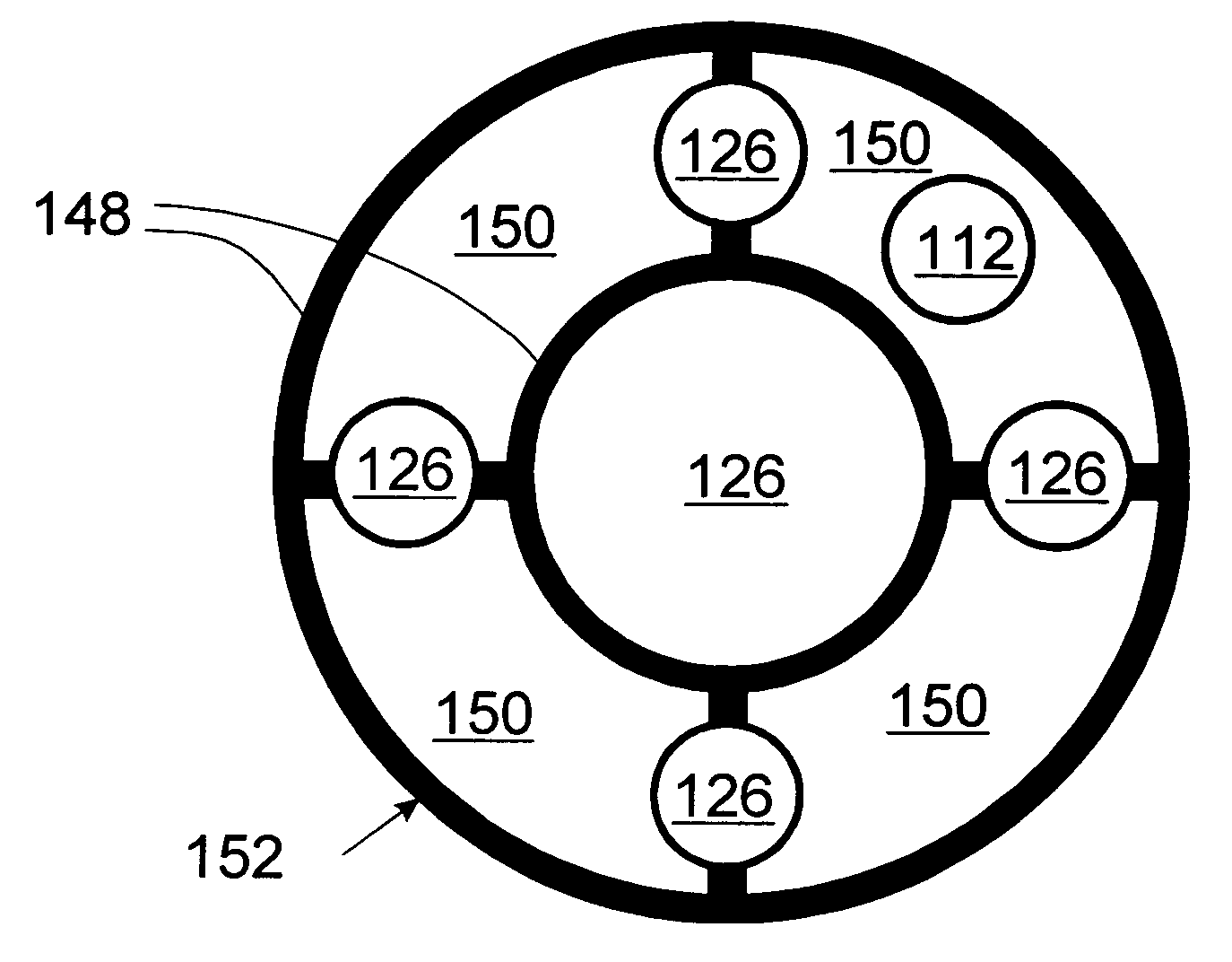
[0077] Briefly described, the present invention provides a polymer common housing having endoscopic elements therein. Example endoscopic elements include, but are not limited to, source light channels (for illumination, hereinafter “light guides”), laser light chan...


PUM


Abstract

An endoscopic shaft having multiple endoscopic elements set in a polymer common housing. The endoscopic elements may be drawn with the common housing to manufacture a component, called an EndoFiber, which forms the length of the endoscopic shaft. A second structure, called an Endocap, may be provided that includes optical elements and which is attached to the end of the EndoFiber to form the shaft.

Description

REFERENCE TO RELATED APPLICATION [0001] This patent application claims priority to U.S. provisional Patent Application No. 60 / 553,144, filed Mar. 15, 2004, and entitled “POLYMER ENDOSCOPIC SHAFT,” incorporated herein by reference.TECHNICAL FIELD OF THE INVENTION [0002] This invention is related to endoscopes and fiberscopes, and more specifically to the shaft of an endoscope or fiberscope. BACKGROUND OF THE INVENTION [0003] Rapid advances in technological innovation over the past decade have transformed the average health care consumer into a buying agent with very high levels of expectation. Concurrent with this consumer trend is the trend in ever increasing health care costs and the regulatory push to contain them. Smaller, quicker, cheaper, more efficacious, and higher quality medical technologies are being sought to replace what have often been highly invasive, costly, and risky procedures in the past. In concert with this overall trend, physicians are seeking new and improved t...

Claims


Application Information

Patent Timeline
IPC IPC(8): A61B1/00A61B1/012A61B1/07
CPCA61B1/012A61B1/07Y10S600/92A61B1/0017A61B1/00165A61B1/0011
Inventor WELKER, DAVID J.BRECKON, CHRISTOPHER D.HOLT, TODD E.RICHTER, CHRISTOPHER A.
Owner PARADIGM OPTICS
Why Eureka
Try Eureka