
Bone tendon bone assembly with allograft bone block

a technology of allograft bone and bone tendon, which is applied in the field of surgical implant products, can solve problems such as bone block crushing, and achieve the effects of accelerating healing, providing overall strength and initial durability of the structure, and effectively promoting new bone growth

Inactive Publication Date: 2005-09-15
MUSCULOSKELETAL TRANSPLANT FOUND INC
View PDF17 Cites 183 Cited by
  • Summary
  • Abstract
  • Description
  • Claims
  • Application Information

AI Technical Summary

Benefits of technology

[0023] It is thus an object of the invention to provide a shaped bone implant construct having a fully mineralized bone block or a partially demineralized cortical bone layer with an interior mineralized bone section to provide compression strength to the implant bone construct.
[0024] It is another object of the invention to utilize a partially demineralized shaped bone implant structure to approximate the mechanical strength characteristics of a natural bone-tendon-bone to provide overall strength and initial durability to the structure.
[0025] It is also an object of the invention to provide a pre-machined bone derived structure which can effectively promote new bone growth and accelerate healing.
[0028] It is also an object of the invention to create a bone-tendon-bone assembly which can be easily handled by the physician during surgery which eliminates or significantly reduces the physician from carving the respective bone blocks.

Problems solved by technology

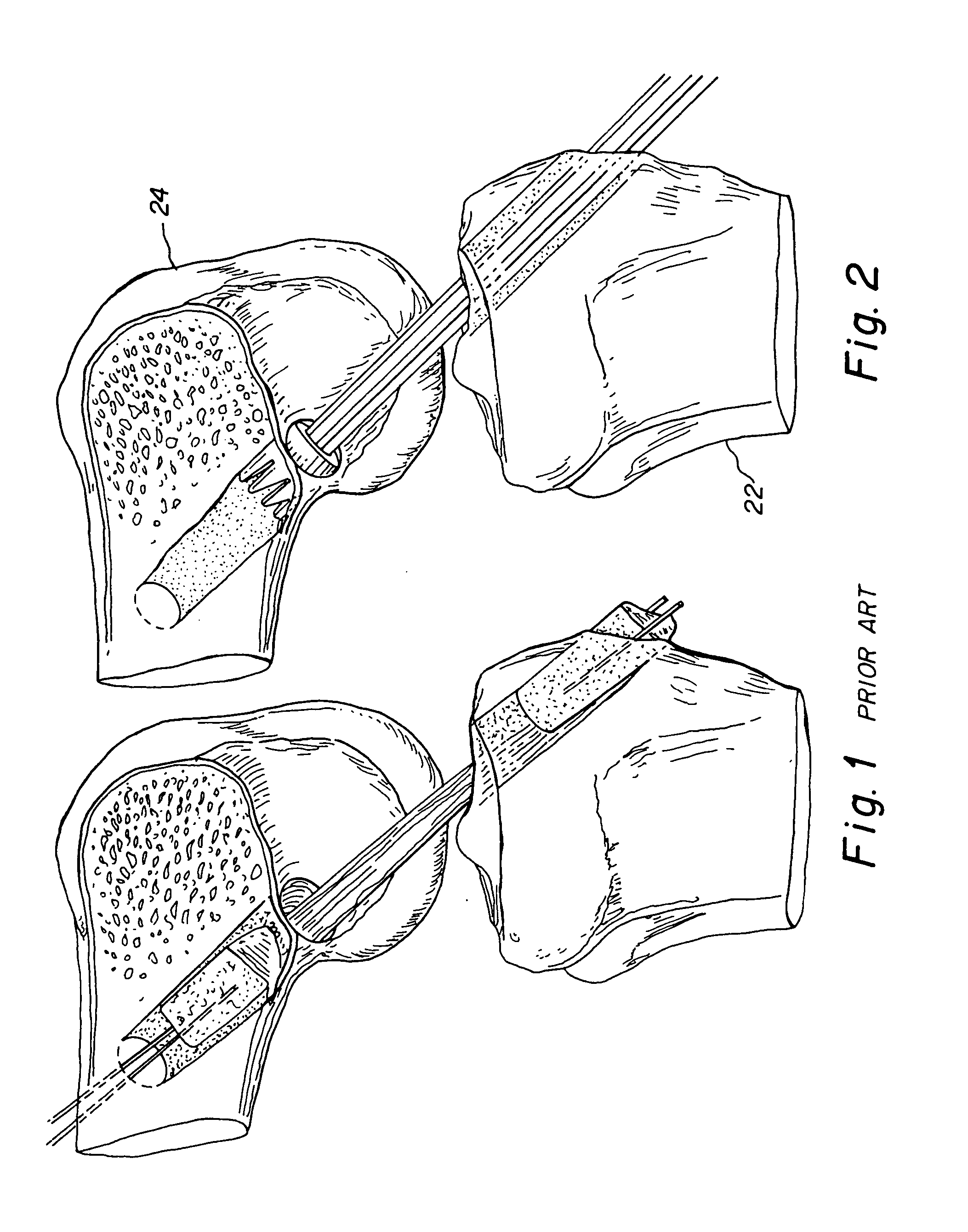
This slot deepening would weaken the bone block by reduction of its effective cross-section so that the bone block might be crushed by the placement of the interference screw and the pressure created on the bone block.

Method used


Image

  • Bone tendon bone assembly with allograft bone block
  • Bone tendon bone assembly with allograft bone block
  • Bone tendon bone assembly with allograft bone block

Examples


Embodiment Construction

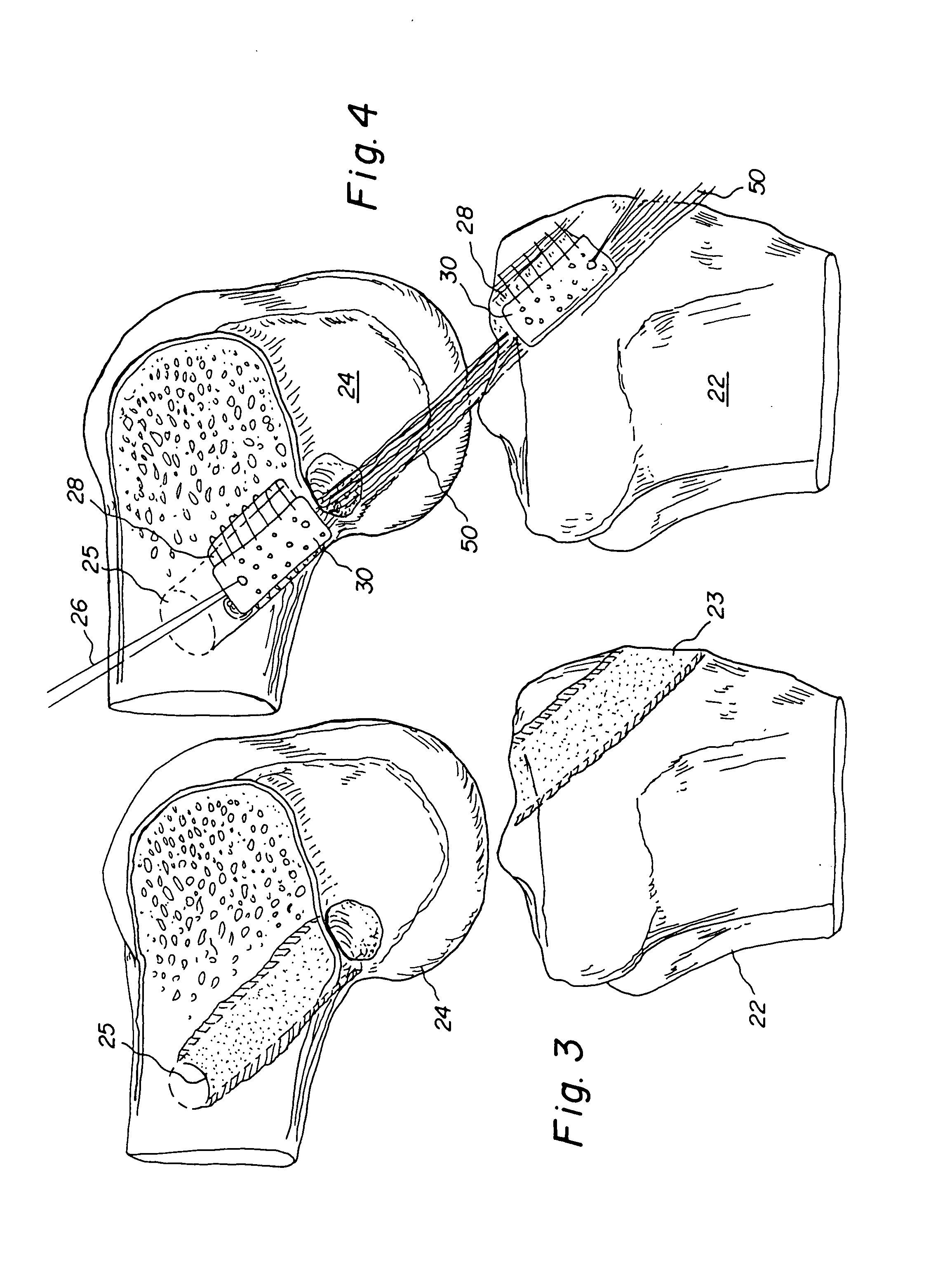
[0048] The preferred embodiment and best mode of the present invention is shown in FIGS. 4-8.

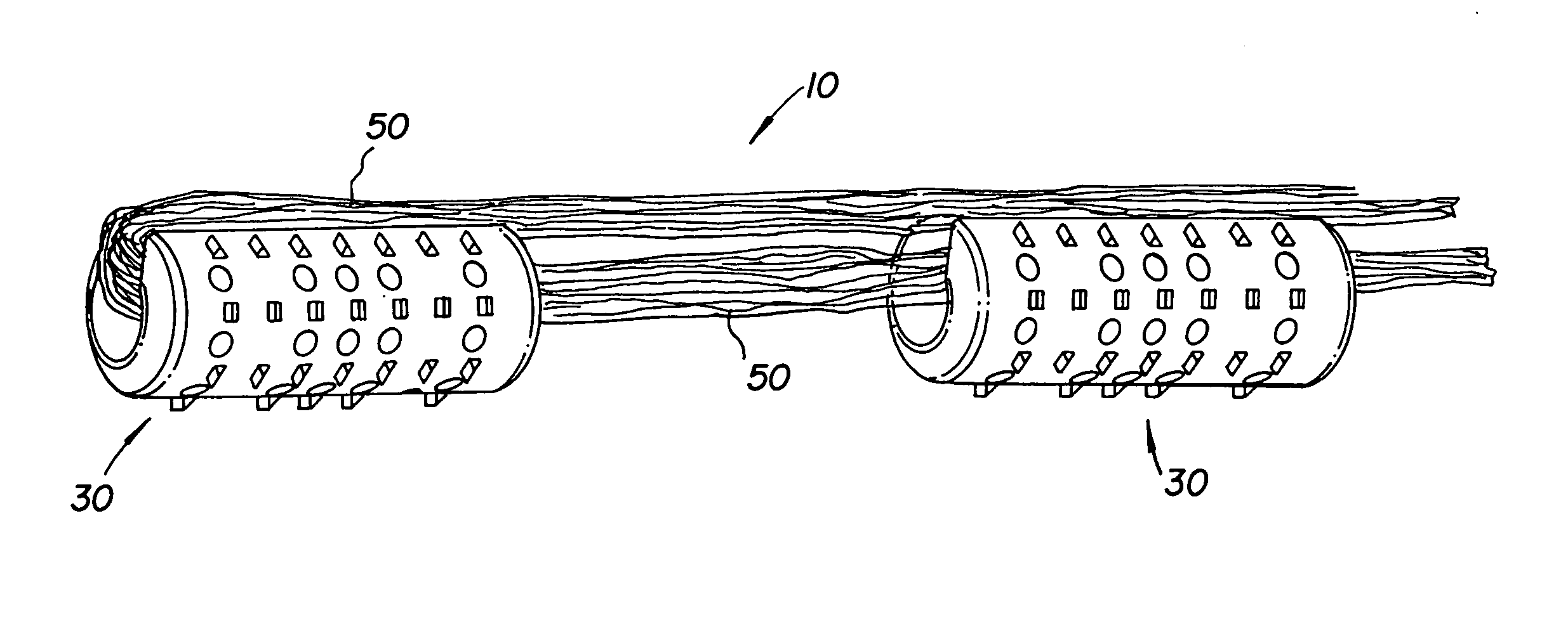
[0049] As shown in the drawings, a reconstructed bone-tendon-bone (B-T-B) assembly 10 for a knee joint is shown in FIG. 4 in accordance with the present invention. The cruciate ligament reconstruction surgical operation can be conducted as an open orthopedic surgery, or through arthroscopic surgery. While the description of the invention is primarily directed to knee reconstruction, the present invention can easily be adapted to other joints requiring ligament or tendon replacement.

[0050] A number of surgical methods and variation of the same can be used in the knee tendon reconstructive surgery. Representative methods which are exemplary but not exclusive or limited are referred to as the Lipscom et al. Technique, the Puddu Technique, the Zaricznyj Technique, the Zarins and Rower Techniques and are set forth and fully explained in Chapter 29, Knee Injuries, Campell's Orthopaedics (1998, 9...


PUM

PropertyMeasurementUnit
angleaaaaaaaaaa
angleaaaaaaaaaa
diameteraaaaaaaaaa

Abstract

The invention is directed toward a bone block, a bone-tendon-bone assembly and method of tendon reconstruction in which at least one tendon replacement is extended between two bone blocks and fixed within each of two bone tunnels in the bones of a joint using interference screws. Each bone block has a central through going bore and at least one substantially parallel channel longitudinally cut in the exterior of the bone block body in which the ligament replacements are seated. One end of each bone block has a rounded recess leading from the central bore to the exterior parallel channel.

Description

RELATED APPLICATION [0001] There are no related applications. FIELD OF INVENTION [0002] The present invention is generally directed toward a surgical implant product and more specifically is a shaped allograft bone-tendon-bone implant assembly. BACKGROUND OF THE INVENTION [0003] Failed ligaments, such as the anterior or posterior cruciate ligaments in the knee joint, significantly limit physical activity and potentially cause chronic knee problems. The anterior cruciate ligament (hereinafter ACL) and the posterior cruciate ligament (PCL) to a lesser extent are often torn during sports related injuries or as result of traumatic stresses. Ligament reconstruction with allograft and autograft tissue has been shown to improve joint function and provide long term improvement in restoration of physical activity. A common surgical method of repair of an ACL is harvesting a patients patellar tendon with bone blocks from the tibia and patella. The bone-patellar tendon-bone implant offers seve...

Claims


Application Information

Patent Timeline
Patent Type & Authority Applications(United States)
IPC IPC(8): A61B17/06A61F2/00A61F2/02A61F2/08A61F2/28A61F2/30A61F2/46A61L27/36A61L27/38
CPCA61B17/06166A61L27/386A61F2/0811A61F2/28A61F2002/0858A61F2002/087A61F2002/2817A61F2002/2839A61F2002/30062A61F2002/30228A61F2002/30235A61F2002/30785A61F2002/30787A61F2002/30881A61F2002/30891A61F2002/30892A61F2002/30894A61F2002/4649A61F2210/0004A61F2230/0069A61F2310/00179A61L27/3604A61L27/3608A61L27/3662A61L27/3695A61F2/08
Inventor STEINER, ANTON J.GERTZMAN, ARTHUR A.
Owner MUSCULOSKELETAL TRANSPLANT FOUND INC
Learn More