Method and apparatus for downhole fluid analysis for reservoir fluid characterization

a reservoir fluid and fluid analysis technology, applied in the field of reservoir fluid characterization, can solve the problem that the commercial development of hydrocarbon fields requires significant amounts of capital

Inactive Publication Date: 2005-09-22
BAKER HUGHES INC
View PDF10 Cites 64 Cited by
  • Summary
  • Abstract
  • Description
  • Claims
  • Application Information

AI Technical Summary

Benefits of technology

[0009] The present invention provides a method and apparatus for real-time downhole detection, distinction and quantification of gases such as C1-C5, H2S, CO2, N2 and other gases and vapors present in a formation fluid sample. The present invention can detect and analyze vapors associated with oil-based drilling fluid and therefore provide a real-time estimate of the percent contamination of the sample by drilling fluid filtrate.
[0012] An ion pump is associated with the evacuated gas analysis chamber to maintain a vacuum in the chamber. The ion pump removes gases, which have diffused from the formation fluid sample into the evacuated chamber on the opposite side of the semi-permeable membrane filter. Alternatively, in place of an ion pump, activated charcoal or some other sorbent could be used to prevent the gases that have diffused into the vacuum from lingering there too long and interfering with the measurement of subsequent gases that have evolved or diffused from a subsequent sample.

Problems solved by technology

Commercial development of hydrocarbon fields requires significant amounts of capital.
It is time consuming to retrieve fluid samples downhole and send them to a surface lab for analysis of gas content Moreover, surface analysis requires removal of the fluid sample and the tool from the borehole for testing the sample before additional exploration and / or production activities occur.

Method used


Image

  • Method and apparatus for downhole fluid analysis for reservoir fluid characterization
  • Method and apparatus for downhole fluid analysis for reservoir fluid characterization
  • Method and apparatus for downhole fluid analysis for reservoir fluid characterization

Examples


Embodiment Construction

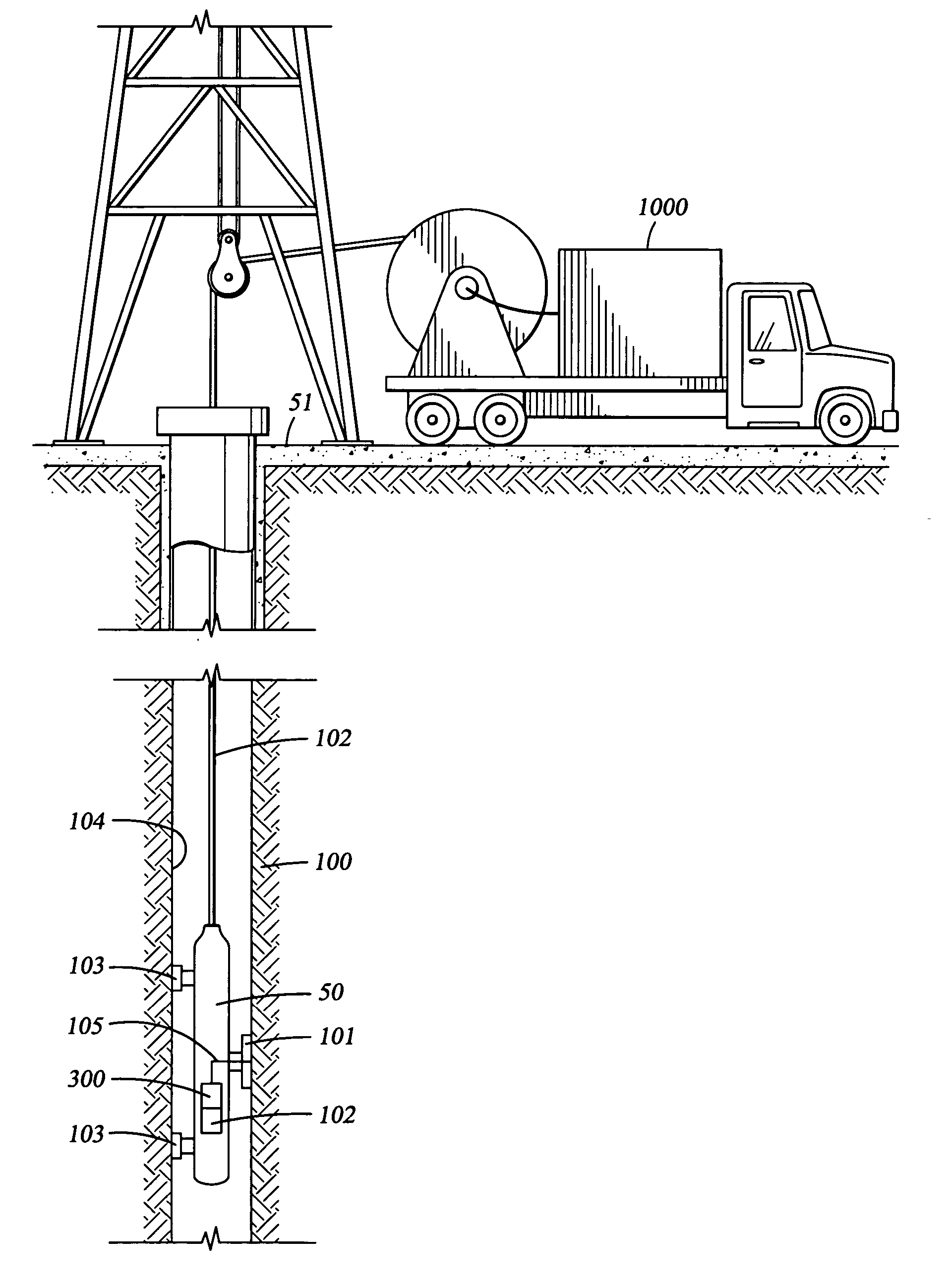
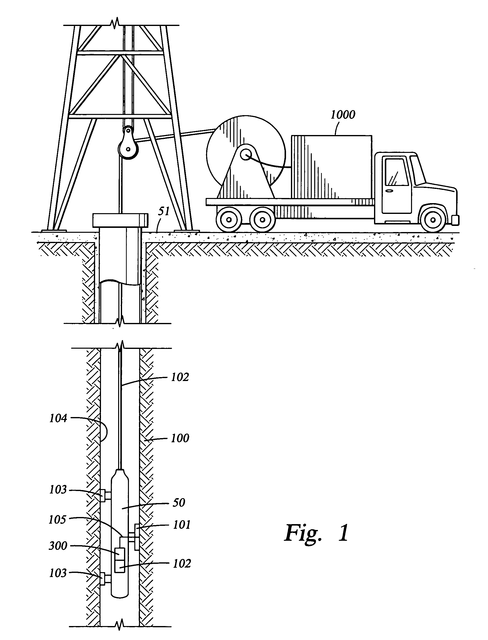
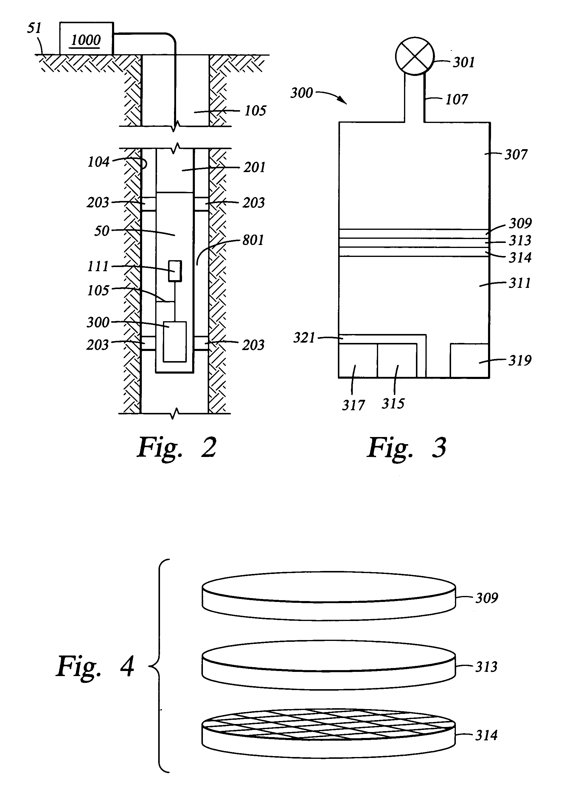
[0024] The present invention provides a method and apparatus for real-time downhole detection, classification and quantification of gases trapped in a representative formation fluid sample. Gases such as C1-C5, H2S, CO2, N2 and other gases and vapors present in a formation fluid sample are quantified by the present invention. The present invention exposes downhole high-temperature high-pressure formation fluid to a semi-permeable membrane such as silicone rubber to permit diffusion of gases from the formation fluid sample into a vacuum chamber containing a residual gas analyzer (RGA). The RGA is a relatively low-resolution mass spectrometer designed for use with high vacuum systems. Higher resolution mass spectrometers can also be used. The RGA is chosen because of its small size and because it is designed for use with high vacuum systems that are typically “baked out”, at 250-300° C. Therefore, many RGA sensors are designed to survive (non-operationally) and operate up to 150° C., ...


PUM


Abstract

A formation fluid sample is exposed to a rigidly-supported semi-permeable membrane such as silicone rubber to permit diffusion of gases and vapors from the formation fluid into a vacuum chamber, while at the same time, blocking the passage of any liquids. The membrane-transmitted gas is analyzed in the vacuum chamber by a residual gas analyzer. An ion pump or sorbent is associated with the evacuated chamber to maintain the vacuum. The ion pump or sorbent removes gases and vapors from the chamber that diffuse into the chamber from the reservoir sample that is on the opposite side of the semi-permeable membrane.

Description

CROSS REFERENCE TO RELATED APPLICATIONS [0001] This patent application claims priority from U.S. provisional patent application No. 60 / 553,921 entitled A Method and Apparatus for Downhole Fluid Analysis for Reservoir Fluid Characterization by Rocco DiFoggio, filed on Mar. 17, 2004 which is incorporated herein by reference in its entirety.BACKGROUND OF THE INVENTION [0002] 1. Field of the Invention [0003] The present invention relates generally to downhole reservoir characterization and in particular to a method and apparatus for real time identification of gases diffused out of a formation fluid sample. Formation fluid samples are obtained and gases are allowed to diffuse from these fluid samples through a semi-permeable membrane into an evacuated chamber. The gases are analyzed in the evacuated chamber by a mass spectrometer or residual gas analyzer (RGA) and a processor which identifies and distinguishes between gases such as C1-C5, H2S, C02, N2 and other gases or vapors present i...

Claims


Application Information

Patent Timeline
Patent Type & Authority Applications(United States)
IPC IPC(8): E21B43/00E21B49/08
CPCE21B49/08H01J49/0422G01N33/2823
Inventor DIFOGGIO, ROCCO
Owner BAKER HUGHES INC
Why Eureka
Try Eureka