Manufacturing method of armature, manufacturing method of motor, and armature

a manufacturing method and technology of armatures, applied in the direction of magnetic circuit rotating parts, magnetic circuit shape/form/construction, magnetic bodies, etc., can solve the problems of deterioration of productivity and inability to maintain the shape by itself, and achieve the effect of reducing size and improving productivity

Inactive Publication Date: 2005-09-22
ASMO CO LTD
View PDF4 Cites 37 Cited by
  • Summary
  • Abstract
  • Description
  • Claims
  • Application Information

AI Technical Summary

Problems solved by technology

However, in general, the coil used for the motor comprises a relatively soft wire such as a thin copper wire, and is unable to maintain its shape by itself.
Hence, after having wound the coil on each tooth, if its end por...

Method used


Image

  • Manufacturing method of armature, manufacturing method of motor, and armature
  • Manufacturing method of armature, manufacturing method of motor, and armature
  • Manufacturing method of armature, manufacturing method of motor, and armature

Examples


first embodiment

[0038] A first embodiment according to the present invention will be described in accordance with FIGS. 1 to 19.

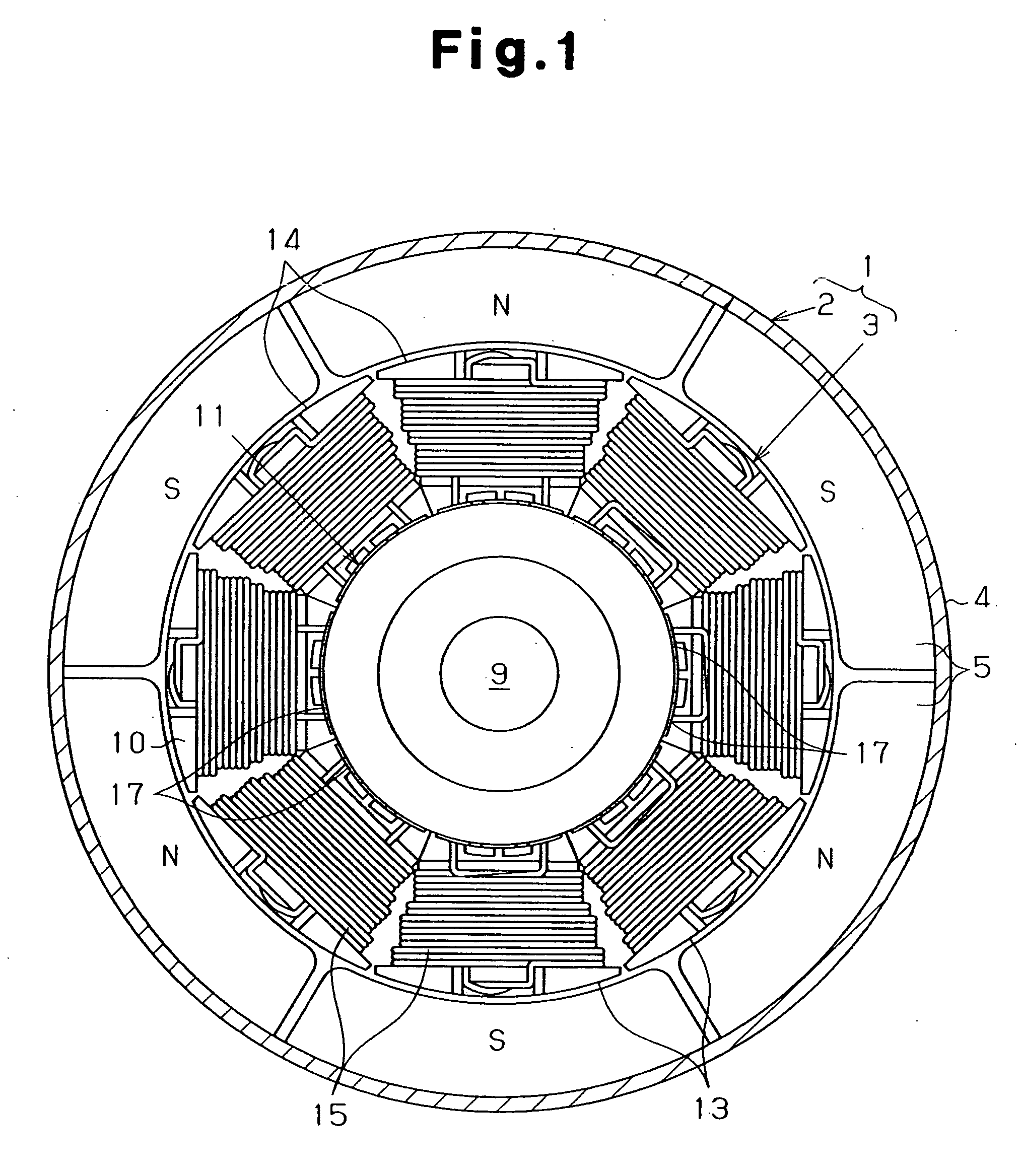
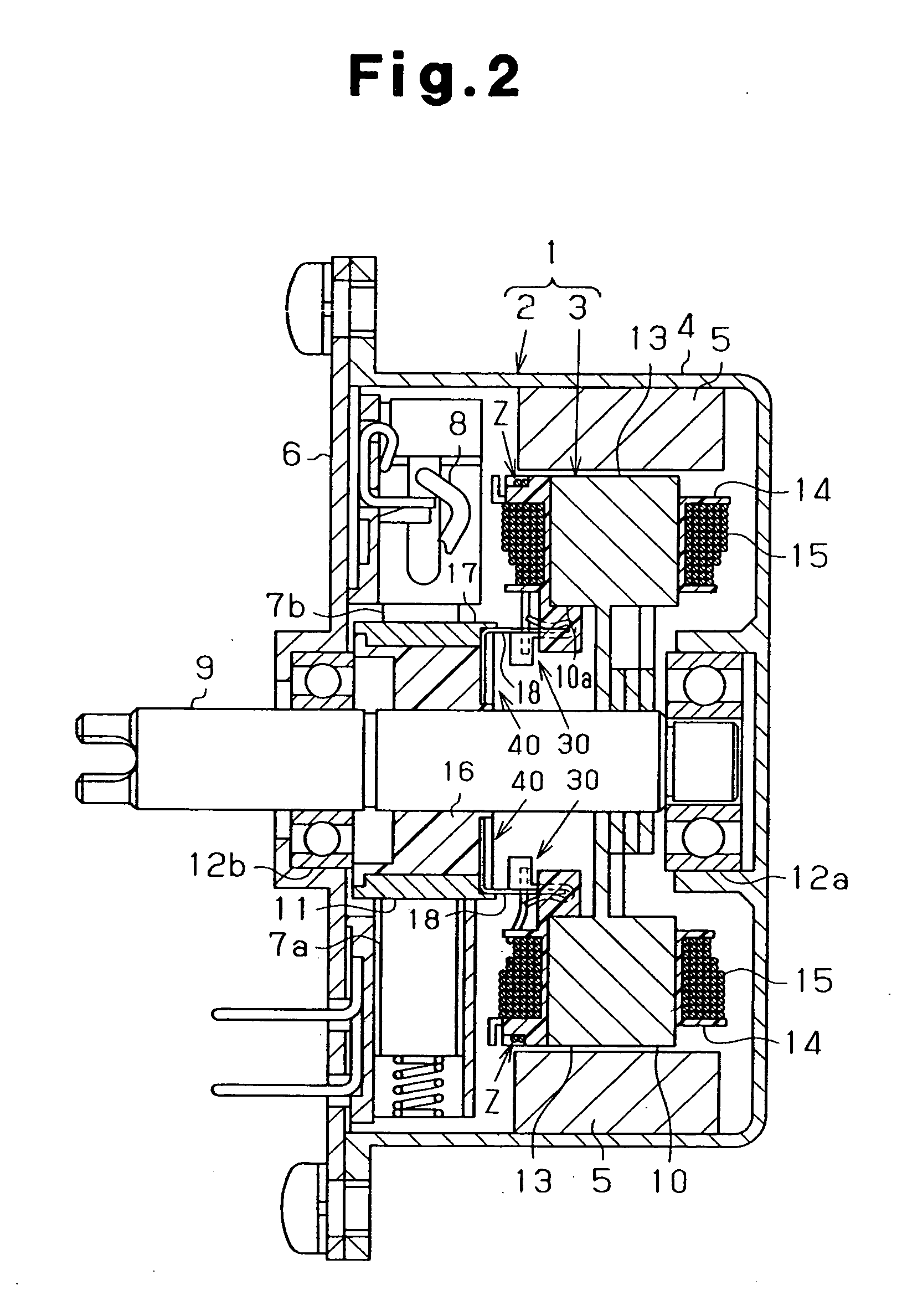
[0039] As shown in FIGS. 1 and 2, a DC motor 1 with brushes according to the present embodiment comprises a stator 2 and an armature 3, which is a rotator.

[0040] The stator 2 comprises a substantially cylindrical yoke housing 4 with one end blocked, and a plurality (six pieces in the present embodiment) of permanent magnets 5 fixed to the inner peripheral surface of the yoke housing 4. The permanent magnets 5 are disposed around the axis of the yoke housing 4 at equal angular intervals so as to become alternately heteropolar in a circumferential direction. An end frame 6 is fixed to an opening end of the yoke housing 4 so as to block the opening of the yoke housing 4. The end frame 6 is held with an anode supply brush 7a and a cathode supply brush 7b. The anode supply brush 7a and the cathode supply brush 7b are connected to a power supply terminal 8.

[0041] The armature ...

fourth embodiment

[0127] In the fourth embodiment, the winding starting end and the winding finishing end of the coil 15 wound about each tooth 13 are fastened individually on the outer protruded portion 27a on the outside in a radial direction of the tooth 13, and spanning up to the wire connection claw 36a of the corresponding terminal 35 along the outer surface of the coil 15. Each end portion of the coil 15 is nipped and joined by a wire connection claw 36a. To be more specific, as shown in FIGS. 27(a) and 27(b), in a state in which the coil 15 is nipped between the sidewall portion 36 and the wire connection claw 36a, the current is allowed to flow while being pressurized by a plus electric pole 163 and a minus electric pole 164 from both sides, and the sidewall portion 36, the end portion of the coil 15, and the wire connection claw 36a are joined together.

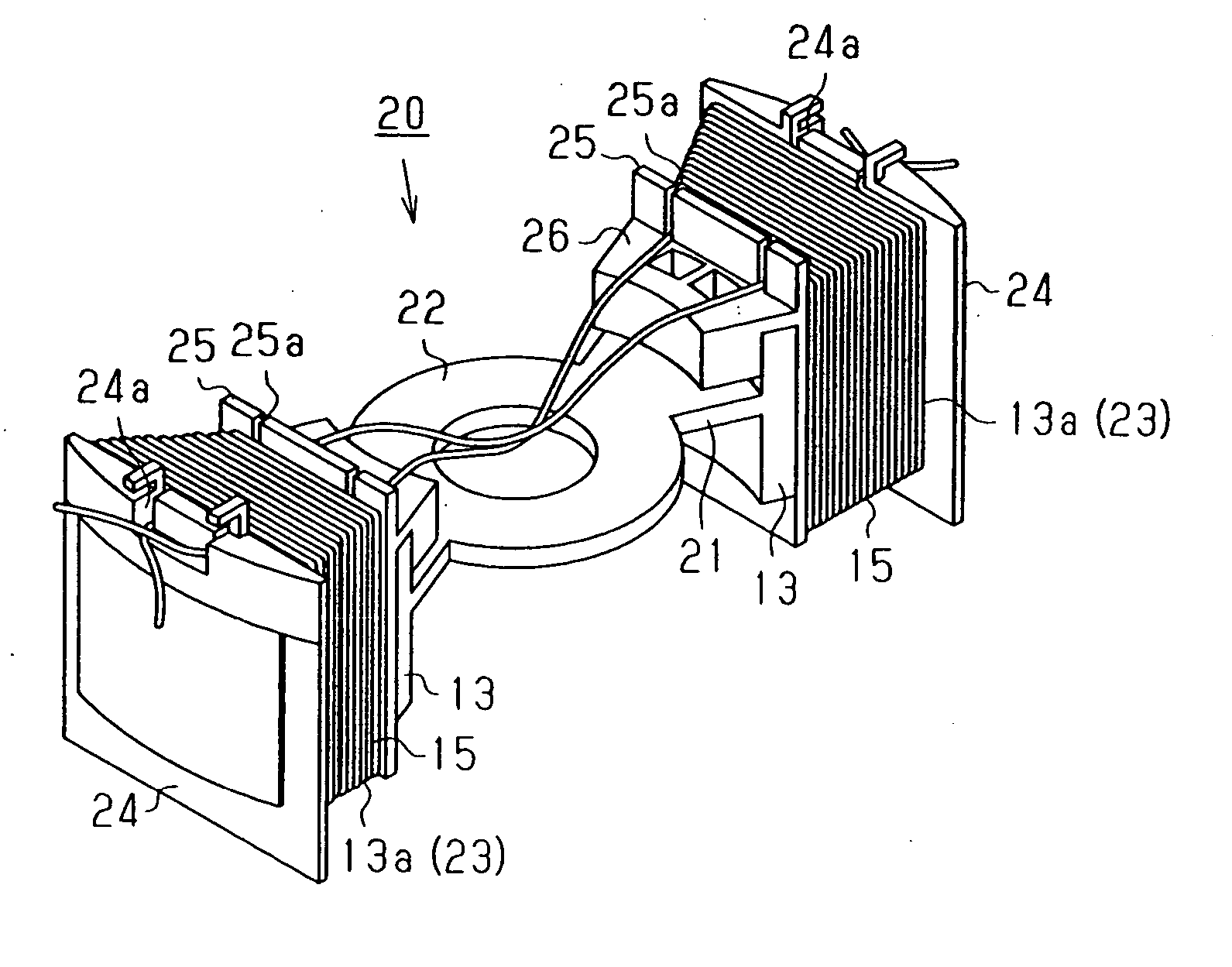
[0128] As shown in FIGS. 28 and 29, four split core members 20 each comprising two coils 15 are assembled so as to be stacked in the axial d...


PUM

PropertyMeasurementUnit
Angleaaaaaaaaaa
Sizeaaaaaaaaaa
Electrical conductoraaaaaaaaaa

Abstract

The armature of a motor comprises a core constituted by assembling a plurality of split core members. Each split core member has at least two teeth. The method for manufacturing the armature comprises the steps of: winding a conductive wire on each tooth of each split core member to form a first coil on the teeth; spanning the conductive wire extending from a winding finishing end of the first coil from each tooth to the other tooth; winding the conductive wire on the tooth to which the conductive wire is spanned to form a second coil on the first coil; joining a winding starting end of the first coil and a winding finishing end of the second coil in each tooth to form a single coil; and mutually assembling the plurality of split core members each comprising the coils. As a result, productivity is improved, while reducing size.

Description

BACKGROUND OF THE INVENTION [0001] The present invention relates to a method for manufacturing an armature, a method for manufacturing a motor, and an armature. [0002] In general, the armature in an electrical machine with rotating parts, such as a motor, has a core that has radially arranged teeth. A coil is wound about each tooth. In the armature having such a core, various configurations have been proposed directed to space factors. For example, a core has been proposed, which is constituted by combining a plurality of split core members having an annular portion and at least one tooth radially extending from the annular portion (see Japanese Laid-Open Patent Publication No. 9-46941, Japanese Laid-Open Utility Model Publication No. 63-187545, Japanese Laid-Open Patent Publication No. 9-322441, Japanese Laid-Open Patent Publication No. 2002-291183, and Japanese Laid-Open Patent Publication No. 2002-369421). In such cores, after winding a coil on the teeth of each split core member...

Claims


Application Information

Patent Timeline
IPC IPC(8): H01R39/32H02K1/00H02K1/08H02K3/00H02K13/04H02K15/095H02K19/00H02K23/02
CPCH01R39/32H02K1/08H02K13/04H02K15/095Y10T29/49071Y10T29/49012Y10T29/49073Y10T29/49009H02K23/02H02K1/148
Inventor YAMAMOTO, TOSHIOKUWANO, MASAYUKIITO, YASUHIDENAKANO, YOSHIKI
Owner ASMO CO LTD
Why Eureka
Try Eureka