Piezoelectric stack and production method of piezoelectric stack

Inactive Publication Date: 2005-09-22
DENSO CORP +1
View PDF3 Cites 27 Cited by
  • Summary
  • Abstract
  • Description
  • Claims
  • Application Information

AI Technical Summary

Benefits of technology

[0017] By performing the firing at an oxygen concentration in the above-described range, the Pb-based glass more readily fills the crystal grain boundary. The crystal grain boundary filled with a Pb-based glass can be made to not allow intrusion of moisture or other substances.
[0018] Therefore, the piezoelectric layer can be protected from a change in phy

Problems solved by technology

This phenomenon gives rise to deterioration in the performance or reduction in the reliability of the piezoelectric stack.
Particularly, when the i

Method used


Image

  • Piezoelectric stack and production method of piezoelectric stack
  • Piezoelectric stack and production method of piezoelectric stack
  • Piezoelectric stack and production method of piezoelectric stack

Examples


example 1

[0050] The piezoelectric stack according to the present invention is described below.

[0051] In the piezoelectric stack of this Example, a piezoelectric layer comprising PZT (lead zirconate titanate) and an internal electrode layer are alternately stacked and the grain boundary-filling factor of a Pb-based glass in the crystal grain boundary inside the piezoelectric layer is 95% or more.

[0052] This is described in detail below.

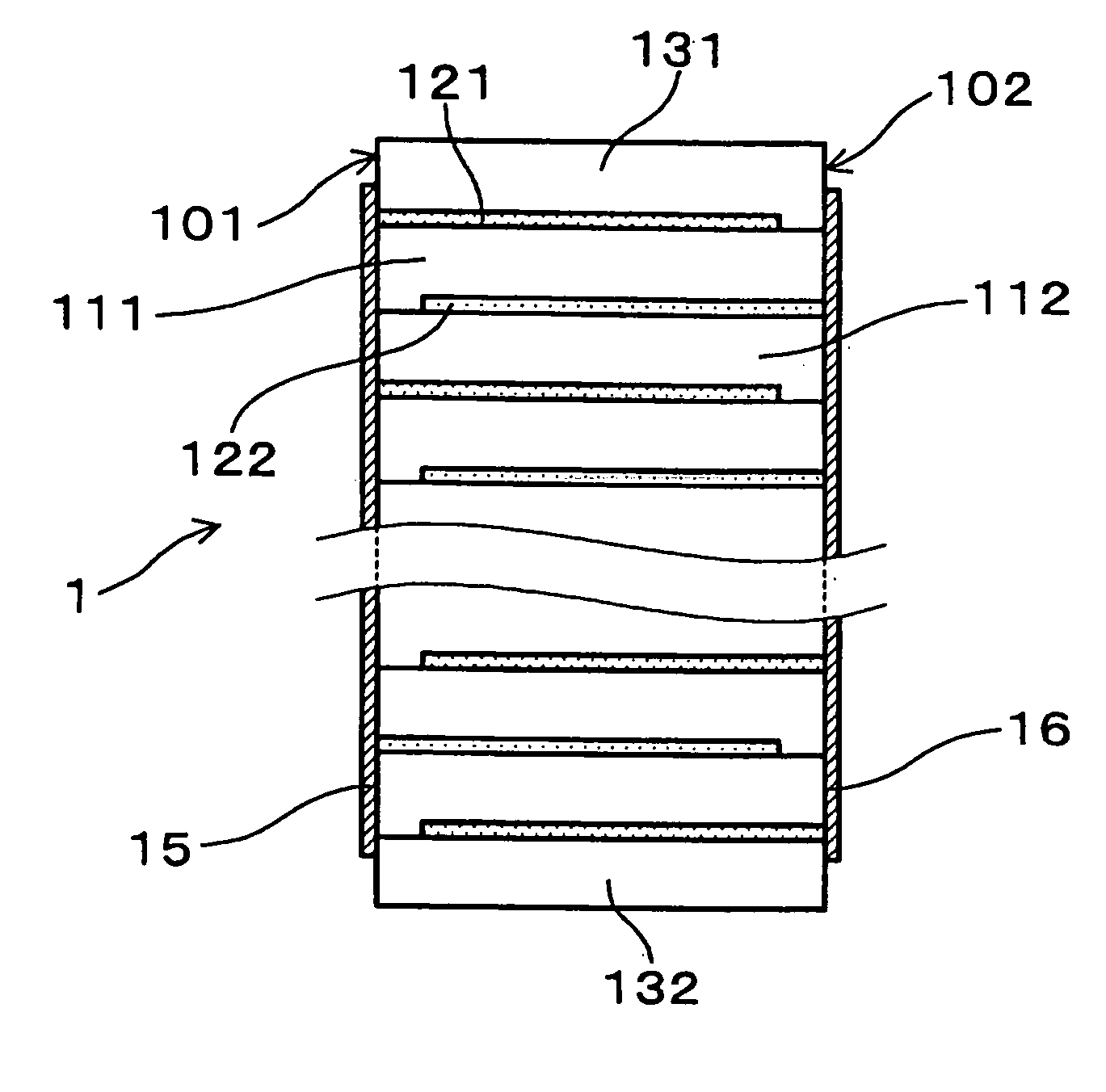
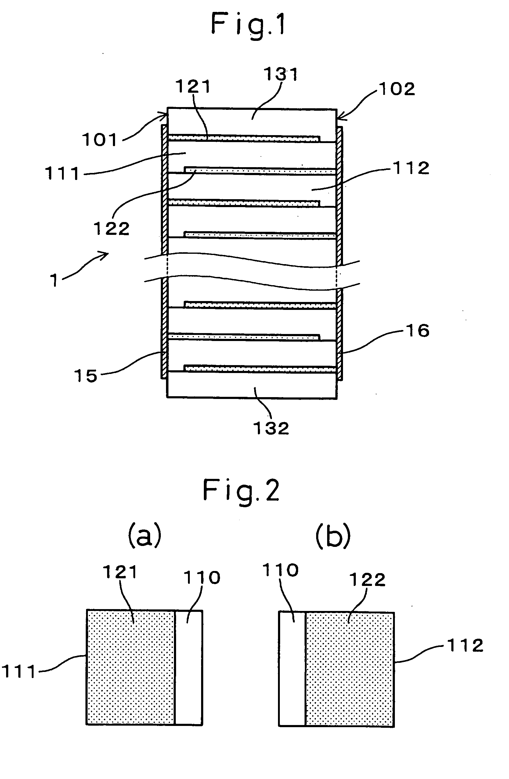
[0053] In the piezoelectric stack of this Example, as shown in FIGS. 1 and 2, a piezoelectric layer 111 where an internal electrode layer 121 is provided in the portion except for the reserved electrode part 110, and a piezoelectric layer 112 where an internal electrode layer 122 is provided in the portion except for the reserved electrode part 110, are alternately stacked.

[0054] The end part of the internal electrode layer 121 is exposed to the side face 101 and the end part of the internal electrode layer 122 is exposed to the side face 102. These exposed...

example 2

[0058] In this Example, the method for producing the piezoelectric stack of Example 1 is described.

[0059] That is, for producing a piezoelectric stack as described in Example 1, in which a piezoelectric layer comprising PZT (lead zirconate titanate) and an internal electrode layer are alternately stacked, unfired sheets for the piezoelectric layer, where Pb is contained in excess of the stoichiometric ratio in PZT (lead zirconate titanate) and an electrically conducting paste for the internal electrode layer is printed, are stacked to produce an unfired stacked body, and the unfired stacked body is fired in an oxygen atmosphere having an oxygen concentration of 40 to 100 vol % such that the grain boundary-filling factor of a Pb-based glass in the crystal grain boundary inside the piezoelectric layer is 95% or more.

[0060] This is described in detail below.

[0061] First, the production of slurry for the piezoelectric layer is described.

[0062] After weighing a raw material powder of...

example 3

[0090] In this Example, the crystal grain boundary-filling factor of a Pb-based glass and the performance of the piezoelectric stack are evaluated.

[0091] Piezoelectric stacks have the partial electrode structure described in Example 1, and were prepared by varying the grain boundary-filling factor. That is, Sample 1 (grain boundary-filling factor: 95%), Comparative Sample C1 (grain boundary-filling factor: 47%) and Comparative Sample C2 (grain boundary-filling factor: 12%). For each of these sample and comparative samples, two piezoelectric stacks were prepared and subjected to the measurements described later.

[0092] Each sample was sealed in an airtight package and left standing in an environment at a temperature of 190° C. for 1 to 1,000 hours. FIG. 5 is a diagram where, if the insulation resistance value before standing is IR0 and the insulation resistance value after standing is IR1, the values of IR1 / IR0 are plotted on the ordinate and the endurance time is taken on the absci...


PUM


Abstract

An object of the present invention is to provide a piezoelectric stack substantially free from deterioration in performance and having high reliability, and a production method thereof. A piezoelectric layer 111, 112 comprising PZT and an internal electrode layer 121, 122 are alternately stacked; the grain boundary-filling factor of a Pb-based glass in the crystal grain boundary of the piezoelectric layer 111, 112 is 95% or more; in producing a piezoelectric stack 1 in which a piezoelectric layer 111, 112 comprising PZT and an internal electrode layer 121, 122 are alternately stacked, unfired sheets for the piezoelectric layer 111, 112 stacked to produce an unfired stacked body, the unfired sheet containing Pb in excess of the stoichiometric ratio in PZT and having printed thereon an electrically conducting paste for the internal electrode layer 121, 122, and the unfired stacked body is fired in an oxygen atmosphere having an oxygen concentration of 40 to 100 vol % such that the grain boundary-filling factor of a Pb-based glass in the crystal grain boundary inside the piezoelectric layer 111, 112 is 95% or more.

Description

FIELD OF THE INVENTION [0001] The present invention relates to a piezoelectric stack usable for a piezoelectric actuator used in a fuel injection device or the like of an automobile, and a production method thereof. BACKGROUND OF THE INVENTION [0002] A piezoelectric actuator employing a piezoelectric stack is sometimes used as a driving source of a fuel injection device for an internal combustion engine of a vehicle such as an automobile. [0003] The piezoelectric stack within the piezoelectric actuator is hermetically sealed in an airtight package to protect it from high-temperature fuel or moisture. [0004] However, the piezoelectric layer of the piezoelectric stack comprises a polycrystalline ceramic and, accordingly, a large number of crystal grain boundaries are present inside the piezoelectric layer. The crystal grain boundary includes gaps as shown in FIG. 6 which is described later. [0005] When the piezoelectric stack is exposed to a high-temperature and closed environment, or...

Claims


Application Information

Patent Timeline
IPC IPC(8): F02M47/02F02M51/00F02M51/06F02M63/00H01L41/083H01L41/18H01L41/187H01L41/22H01L41/273H01L41/297H01L41/39H02N2/00
CPCF02M63/0026F02M2200/21H01L41/273H01L41/1876H01L41/083H10N30/50H10N30/053H10N30/8554
Inventor KOBANE, YOICHIFUJII, AKIRAKAMIYA, HIDEOMAKINO, HIROAKI
Owner DENSO CORP
Why Eureka
Try Eureka