

Flat panel fluorescent lamp and fabricating method thereof
- Summary
- Abstract
- Description
- Claims
- Application Information
AI Technical Summary
Benefits of technology
Problems solved by technology
Method used
Image

Examples
first embodiment
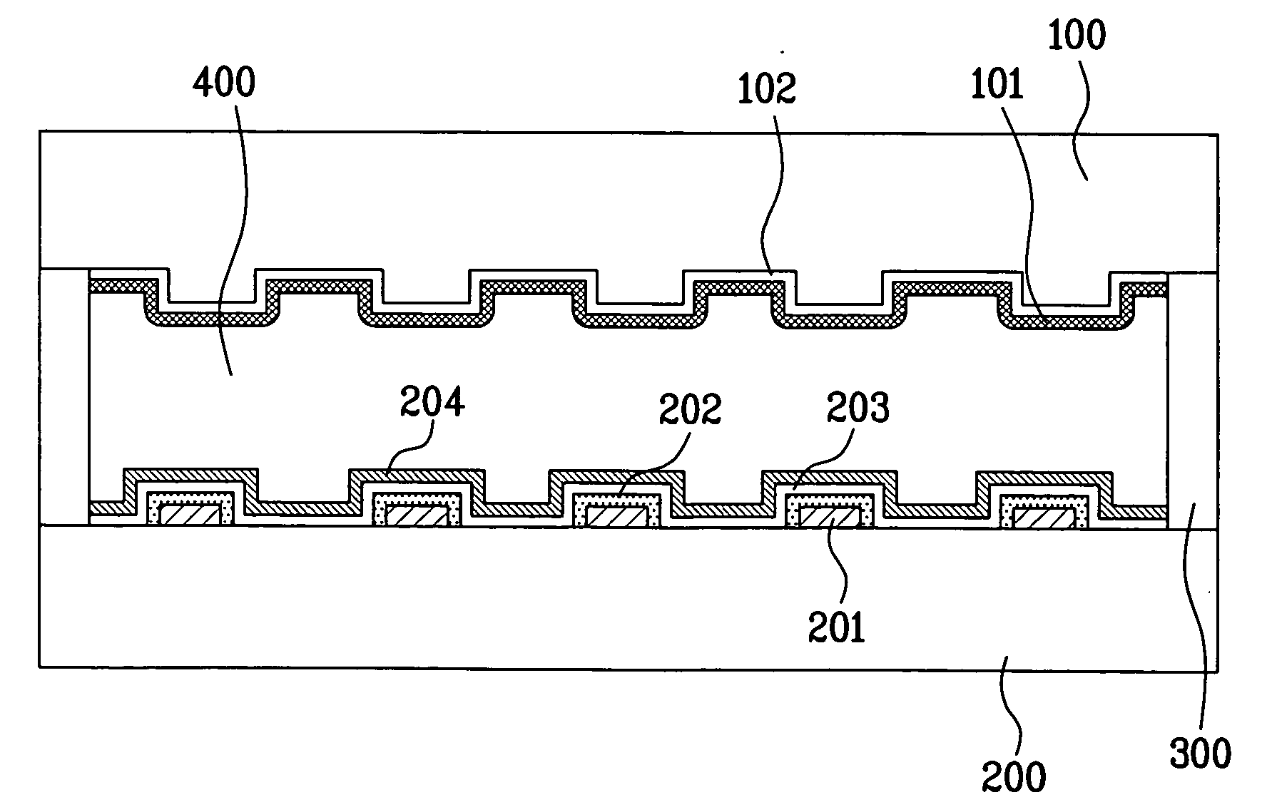
[0108]FIG. 6 is a cross-sectional diagram of a flat panel fluorescent lamp according to the present invention, in which the assembly of the upper plate in FIG. 4A and the lower plate in FIG. 5A is illustrated.
[0109] Referring to FIG. 6, a flat panel fluorescent lamp according to a first embodiment of the present invention includes an upper plate 100 having a plurality of prominences and depressions on its surface, a first fluorescent layer 101 on the upper plate 100 having the prominences and depressions, a lower plate 200 forming a hermetic space with the upper plate 100 to have a predetermined gap from the upper plate 100, a plurality of electrodes 201 on the lower plate 200 having a uniform distance from each other, an insulating layer 202 enclosing each of the electrodes 201, a reflective layer 203 on an entire surface of the lower plate 200 including the insulating layer 202 and electrodes 201, a second fluorescent layer 204 on the reflective layer 203, a spacer 300 between edg...
second embodiment
[0118]FIG. 7 is a cross-sectional diagram of a flat panel fluorescent lamp according to the present invention, in which the assembly of the upper plate in FIG. 4B and the lower plate in FIG. 5A is illustrated.
[0119] Referring to FIG. 7, a flat panel fluorescent lamp according to a second embodiment of the present invention includes an upper plate 100 having a plurality of prominences and depressions on a surface of its backside, a transparent electrode 102 on the upper plate 100 including the prominences and depressions, a first fluorescent layer 101 on the transparent electrode 102, a lower plate 200 forming a hermetic space with the upper plate 100 to have a predetermined gap from the upper plate 100, a plurality of electrodes 201 on the lower plate 200 having a uniform distance from each other, an insulating layer 202 enclosing each of the electrodes 201, a reflective layer 203 on an entire surface of the lower plate 200 including the insulating layer 202 and electrodes 201, a se...
third embodiment
[0127]FIG. 8 is a cross-sectional diagram of a flat panel fluorescent lamp according to the present invention, in which the assembly of the upper plate in FIG. 4C and the lower plate in FIG. 5A is illustrated.
[0128] Referring to FIG. 8, a flat panel fluorescent lamp according to a third embodiment of the present invention includes an upper plate 100 formed of a transparent material, a plurality of ball type transparent particles 104 on the upper plate 100, a first fluorescent layer 101 on an entire surface of the upper plate 100 including the transparent particles 104, a lower plate 200 forming a hermetic space with the upper plate 100 to have a predetermined gap from the upper plate 100, a plurality of electrodes 201 on the lower plate 200 having a uniform distance from each other, an insulating layer 202 enclosing each of the electrodes 201, a reflective layer 203 on an entire surface of the lower plate 200 including the insulating layer 202 and electrodes 201, a second fluorescen...
PUM
 Abstract
Description
Claims
Application Information