Antenna duplexer

a duplexer and duplexer technology, applied in the field of duplexers, can solve the problems of circuit deterioration in electrical or physical characteristics, large current consumption must also be accepted, and harmonic components generated in signal transmission or intermodulation generated in signal reception are likely to occur,

Active Publication Date: 2005-09-22
SKYWORKS PANASONIC FILTER SOLUTIONS JAPAN
View PDF8 Cites 32 Cited by
  • Summary
  • Abstract
  • Description
  • Claims
  • Application Information

AI Technical Summary

Problems solved by technology

A large current consumption must also be accepted due to the switching circuit provided additionally.
Even if the current consumption is restrained to a low level, the problem is that signal distortions such as harmonic components generated in signal transmission or intermodulation generated in signal reception are likely to occur due to a non-linearity of the switching circuit.
Additionally, switching circuits or surface acoustic wave (SAW) filters used in the antenna duplexer must accept problems of deterioration in electrical characteristics of the antenna duplexer itself or peripheral circuits due to undesired surge pulses intruding through the antenna terminal.
Particularly, switching circuits near the antenna or adjacent circuits are likely to be influenced by the surge pulses, causing in some case the circuits to deteriorate in electrical or physical characteristics.

Method used


Image

  • Antenna duplexer
  • Antenna duplexer
  • Antenna duplexer

Examples


exemplary embodiment 1

[0020] Exemplary embodiment 1 is described with reference to drawings.

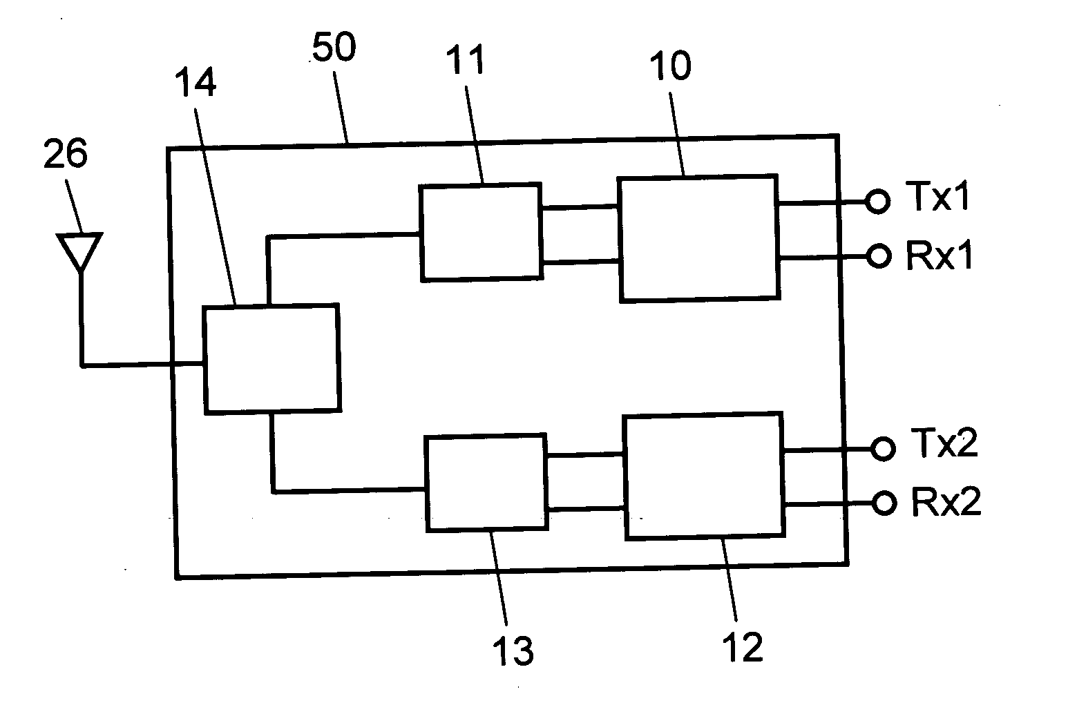
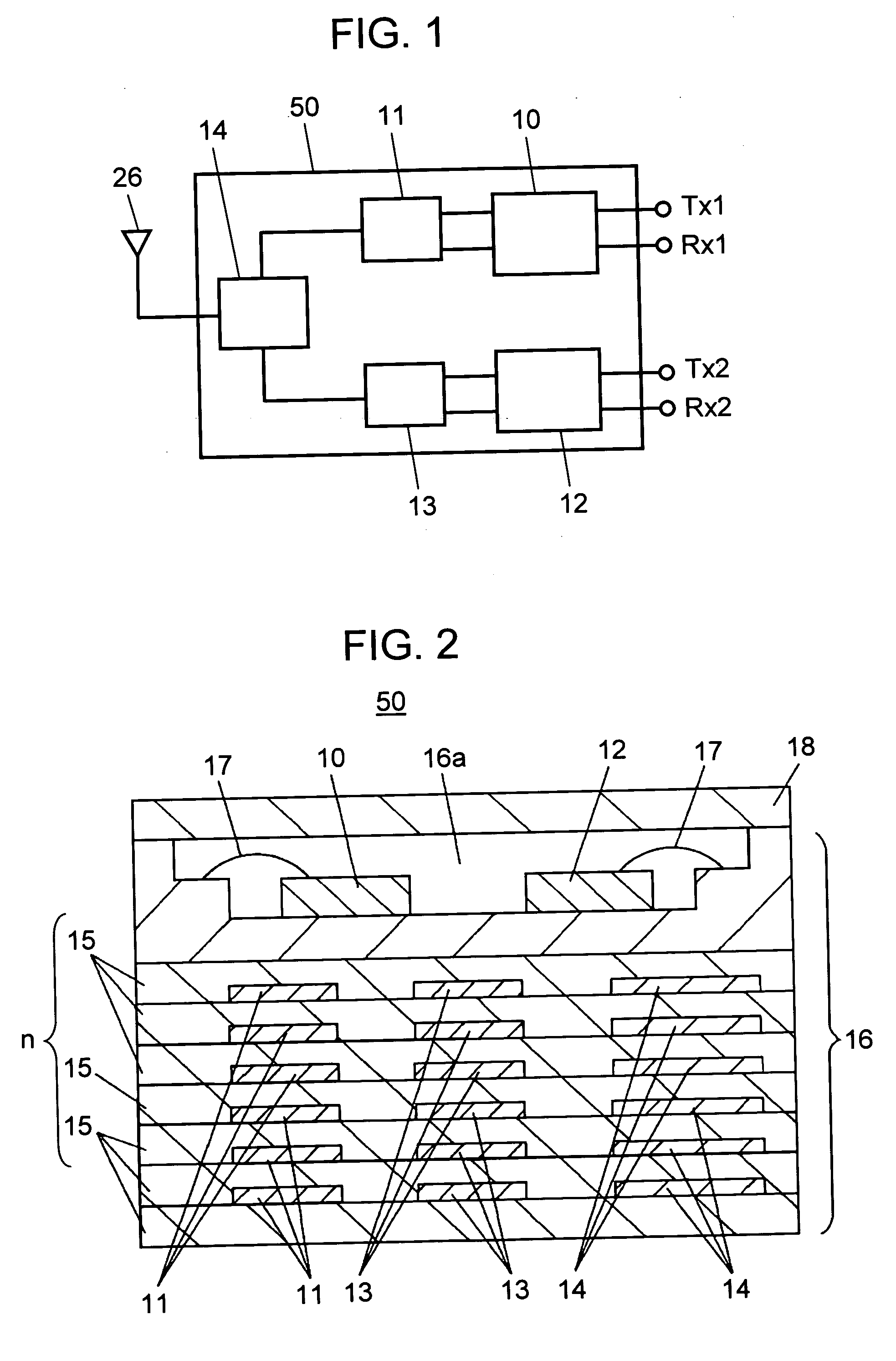
[0021]FIG. 1 illustrates a circuit block diagram of an antenna duplexer used in exemplary embodiment 1 of the present invention. Antenna duplexer 50 is provided with first SAW filter 10. First SAW filter 10 includes a transmission filter (not shown) to pass frequencies ranging 824 to 849 MHz and a reception filter (not shown) to pass frequencies ranging 869 to 894 MHz. First phase shift circuit 11 is provided for impedance matching by phase shifting. Additionally, first SAW filter 10 and first phase shift circuit 11 form a duplexer for low channel frequency band to be used for instance in CDMA (Code Division Multiple Access) system of 800 MHz band.

[0022] Here, the diplexer differs from the duplexer in that: the diplexer locating at the head from an antenna is a filter device to select a double-frequency band or so called a dual band, but the duplexer locating at the way to the antenna plays a role of transmissio...

exemplary embodiment 2

[0040] Next, exemplary embodiment 2 is described with reference to FIG. 7.

[0041] Exemplary embodiment 2 differs from exemplary embodiment 1 in following points: diplexer 14 selects double-frequency band signals or so called dual band signals that includes low channel or low frequency 800 MHz band signals and high channel or high frequency 1.9 GHz band signals in exemplary embodiment 1, on the contrary, a phase shift circuit performs a phase matching of duplexers for different frequency bands in exemplary embodiment 2.

[0042]FIG. 7 shows antenna duplexer 50. Antenna duplexer 50 includes a low channel of 800 MHz band duplexer including first SAW filter 10 and first phase shift circuit 11. Second SAW filter 12 together with second phase shift circuit 13 forms a 1.9 GHz high frequency band duplexer. Here, if enough out-of-pass band attenuation amount in respective 800 MHz band and 1.9 GHz band are obtained, diplexer 14 needs not to select signals as attenuation characteristics like in ...

exemplary embodiment 3

[0048] Next, exemplary embodiment 3 is described with reference to FIG. 9.

[0049] Exemplary embodiment 3 differs from exemplary embodiment 1 in following points: first SAW filter 10, first phase shift circuit 11, second SAW filter 12, second phase shift circuit 13 and diplexer 14 are described formed in a monolithic structure in exemplary embodiment 1; on the contrary, only first SAW filter 10, first phase shift circuit 11 and diplexer 14 are formed in a monolithic structure in exemplary embodiment 3.

[0050]FIG. 9 shows a duplexer comprising first SAW filter 10 and first phase shift circuit 11 for a low channel of 800 MHz band signals. Phase shift circuit 11 connects to diplexer 14. 1.9 GHz terminal of diplexer 14 connects to external terminal 29. External terminal 29 of antenna duplexer 50 connects to duplexer 30 to be used for 1.9 GHz band. This can form antenna duplexer for both 800 MHz band and 1.9 GHz band. Duplexer 30 includes second SAW filter 12 and second phase shift circui...


PUM


Abstract

The disclosed is a downsized and power saving antenna duplexer. The antenna duplexer includes: diplexer; first surface acoustic wave filter to transmit / receive low channel frequency band signals; first phase shift circuit to match the transmission phase with the reception phase of first surface acoustic wave filter; second surface acoustic wave filter to transmit / receive high channel frequency band signals; second phase shift circuit to match the transmission phase with the reception phase of second surface acoustic wave filter. Diplexer, first phase shift circuit and second phase shift circuit are formed in a monolithic structure in package that includes surface acoustic wave filters. The configuration can provide the antenna duplexer with a compact size, a lower current consumption and a highly efficient performance.

Description

TECHNICAL FIELD [0001] The present invention relates to an antenna duplexer, particularly used in cell-phones or the like, for transmitting and receiving a plurality of frequency band signals. BACKGROUND ART [0002]FIG. 10 shows an example of conventional antenna duplexer schematically. The example employs a system having a plurality of antenna duplexers 1 and 2 housed in one package 5, selecting respective antenna duplexers by switch 3. In FIG. 10, switch 3 connects to antenna 4. Antenna duplexer 1 includes transmission terminal Tx1 and reception terminal Rx1 respectively. Antenna duplexer 2 includes similar terminals Tx2 and Rx2 respectively. Another known system (not shown) is to select one of antenna duplexers provided separately using a switching circuit. [0003] A conventional art related to the present invention is disclosed for instance in Japanese Patent Laid-Open Application No. 2000-349586. [0004] In a conventional art, generally, a large overall size of the antenna duplexe...

Claims


Application Information

Patent Timeline
Patent Type & Authority Applications(United States)
IPC IPC(8): H03H7/46H03H9/72H04B1/00H04B1/50H04B1/52
CPCH03H7/465H03H9/0576H04B1/52H04B1/0057H03H2250/00
Inventor SATOH, YUKINISHIDA, KAZUSHI
Owner SKYWORKS PANASONIC FILTER SOLUTIONS JAPAN
Why Eureka
Try Eureka