Eureka AIR delivers breakthrough ideas for toughest innovation challenges, trusted by R&D personnel around the world.

Liquid crystal display unit

Inactive Publication Date: 2005-09-22
NITTO DENKO CORP
View PDF11 Cites 14 Cited by
  • Summary
  • Abstract
  • Description
  • Claims
  • Application Information

AI Technical Summary

Benefits of technology

[0020] The present invention has been made to solve the problems associated with the above prior arts. It is a first object of the present invention to provide a liquid crystal display device that provides a wide viewing angle and an excellent display quality without occurrence of Moire fringes or interference patterns. It is a second object of the present invention to provide a liquid crystal display device that is capable of being manufactured in a thin, low-profile configuration.
[0021] In order to achieve the first object of the present invention, there is provided a liquid crystal display device which includes a backlight, a collimating element for collimating incoming light from the backlight and transmitting the collimated light, a liquid crystal cell for allowing the light coming from the collimating element to pass therethrough, and a viewing angle widening element for widening the viewing angle by diffusing the light transmitted through the liquid crystal cell, in which the collimating element does not have a periodic pattern structure that allows Moire fringes or interference patterns seen in optical observation from a display side to be formed relative to a periodic pattern structure of another optical member of the liquid crystal display device.
[0022] According to the present invention, the collimating element for transmitting the collimated light to the liquid crystal cell and the viewing angle widening element for widening the viewing angle by diffusing the light transmitted through the liquid crystal cell achieves a liquid crystal display device with wide viewing angle. Also, with the collimating element which does not have a periodic pattern structure that allows Moire fringes or interference patterns seen in optical observation from a display side to be formed relative to a periodic pattern structure of another optical member (the liquid crystal cell, the viewing angle widening element or the like) of the liquid crystal display device, the liquid crystal display device as provided provides a high quality display without occurrence of Moire fringes or interference patterns.
[0024] According to the present invention, the transmission wavelength band of the bandpass filter is optimized so that only the light collimated toward the front side can be transmitted. Since the bandpass filter is formed such as by vapor deposition of a material into a multilayer structure, it does not have a periodic pattern structure that allows Moire fringes or interference patterns to be formed relative to a periodic pattern structure of another optical member of the liquid crystal device. This is also significantly advantageous in the fact that the vapor deposition of a material can achieve a thin layered structure, a thin bandpass filter and hence a thin low-profile liquid crystal display device.
[0028] The collimation degree of the light coming from the collimating element is preferably within ±20° so that an area of a conventional TN liquid crystal display device with a high contrast ratio can efficiently be utilized. The collimation degree of the light is more preferably within ±15° and further preferably within ±10°.
[0031] According to the present invention, since the viewing angle widening element does not substantially cause backscattering, it is possible to prevent lowering of the transmittance due to the presence of the viewing angle widening element. Also, since the viewing angle widening element does not substantially destroy a polarized state, it can be located adjacent to the liquid crystal cell (e.g., between the liquid crystal cell, and a polarizer on the display side of the liquid crystal cell), thus preventing influences from blurred pixels of the liquid crystal cell or the like.

Problems solved by technology

In a liquid crystal display device to which the above viewing angle widening method is applied, a technique realizing the collimation of the backlight causes various practical problems.
Hei-10-333147 and Hei-10-255528), there cause various problems when putting such a technology into practical use, such as a thick profile backlight, deteriorated efficiency in light utilization and increased costs.
These approaches therefore are hard to meet the requirements expected as the viewing angle widening element for LCDs.
The optical system such as BEF, which relies on a prism effect which distorts the light due to the refractive index difference between an irregular film surface and air, is impossible to be laminated to another film with an adhesive agent or tackiness agent since it necessarily needs an air interface therebetween.
This causes a problem that during the fabrication process, dusts or foreign matters are trapped in the air interface or a surface is damaged.
Where a light-shielding louver film (e.g., a light control film manufactured by 3M Corporation) as illustrated in FIG. 6 is used as a conventionally existing collimating element, light absorption loss is significant, causing a brightness problem.
In this case, a maximum transmittance of about 90% is secured and the collimation reaches a good level as well, but a problem of increasing the thickness arises.
As described above, where the light-shielding louver film is used as the collimating element, the thickness, transmittance (brightness) or collimation degree is necessarily deteriorated and therefore many practical problems are caused.
In the collimating element using the aforementioned light-shielding louver film, a microlens array, a microprism array or the like, Moire fringes are formed between their fine pattern structure and pixels of a liquid crystal cell, causing difficulty to produce a good display.
In order to prevent occurrence of Moire fringes, a diffusing element may be inserted into a portion on the light emission side of the collimating element, but poses a problem of deteriorating the collimation degree.
This poses a problem that Moire fringes or interference patterns are easy to occur even between members which have been treated so as not to occur Moire fringes or interference patterns, that is, between the viewing angle widening element and the collimating element.
The same is applied to the arrangement manner (angle, alignment, etc.) of both elements, and therefore there is a problem that the permissible design flexibility is necessarily limited in view of the prevention of occurrence of Moire fringes or interference patterns; in other words, the selectable range of the optical system for these elements is greatly limited.
However, with hologram materials, only a small effect of lowering the transmittance of oblique incident light can be produced by allowing perpendicularly incident light to pass therethrough while diffusing the oblique incident light.
Where the hologram is located in a diffusing light source (backlight), it is difficult to converge highly directional light rays.
Also, hologram materials are soft and therefore easy to be affected by stress distortion, posing a problem of deteriorating the optical reliability.
As described above, a conventional liquid crystal display device equipped with the collimating element and the viewing angle widening element has a limited design flexibility for the optical reason resulting from the fine pattern structure of both the elements and therefore there is a problem of making it difficult to put a liquid crystal display device with a high quality display into practical use.

Method used


Image

  • Liquid crystal display unit
  • Liquid crystal display unit
  • Liquid crystal display unit

Examples


examples

[0079] Examples and Comparative Examples as presented will make the characteristics of the present invention more clear.

example 1

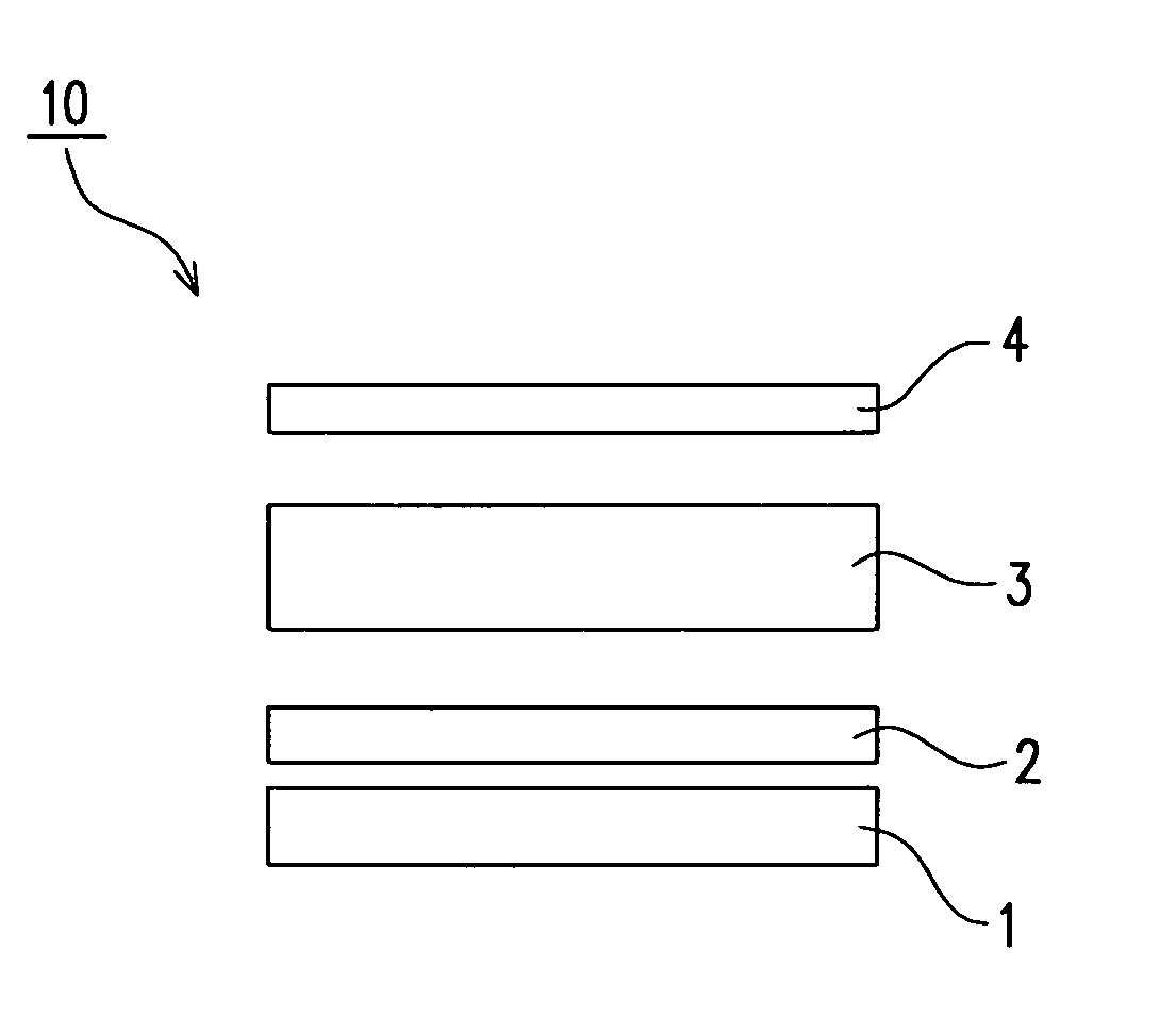
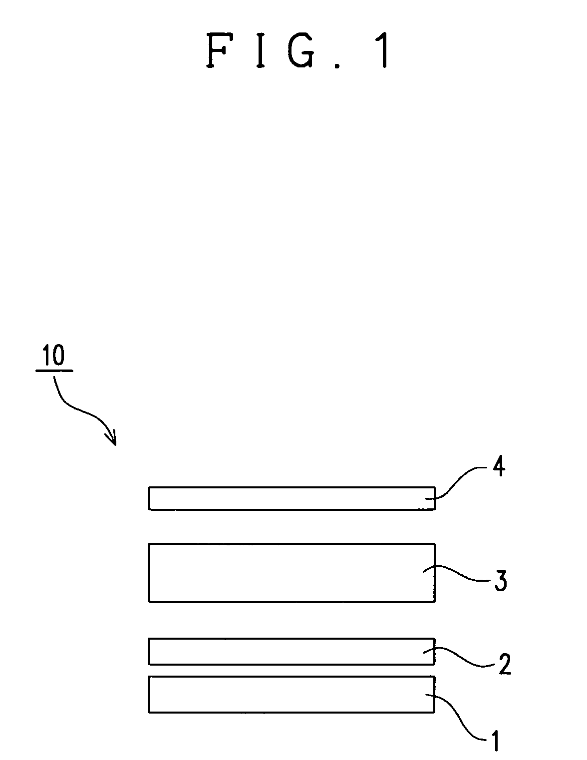
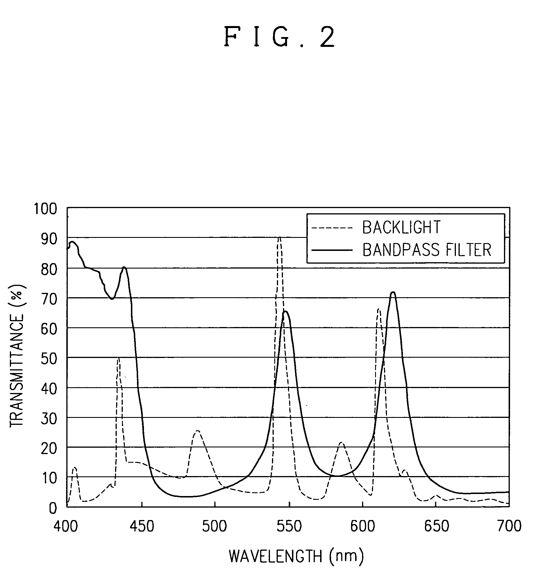
[0080] Fifteen layers of vapor-deposited thin films of TiO2 / SiO2, respectively having thickness as designed in Table 1, were laminated on a substrate of a polyethylene terephthalate film having a thickness of 50 μm (a total thickness: about 53 μm) to prepare a bandpass filter having the transmission spectral characteristics, as illustrated in FIG. 2.

TABLE 1FILMTHICKNESSLAYERMATERIAL[nm]15TiO292.114SiO2130.113TiO268.312SiO297.211TiO263.210SiO288.29TiO2152.18SiO292.87TiO270.76SiO250.35TiO2148.64SiO295.83TiO265.52SiO296.91TiO265.3SUBSTRATE

[0081] With the diffusing plate mounted on an optical transmission member of a conventional non-directional backlight (the emission spectrum of a cold cathode light source used is shown in FIG. 2) and the bandpass filter mounted thereon, it has been found that the light transmitted through the bandpass filter is collimated to about ±20° relative to the front.

[0082] The optical system was incorporated into a TFT liquid crystal panel having viewing a...

example 2

[0084] A fluorinated acrylate resin (LR202B manufactured by Nissan Chemical Industrials, Ltd.) as a low refractive index material, and an acrylate resin with ultrafine particles of a high refractive index inorganic material embedded therein (DeSolite manufactured by JSR Corporation) as a high refractive index resin were respectively used. A total of twenty-one layers of them having designed thicknesses shown in Table 2 were laminated on a substrate (TAC film (TD-TAC)) manufactured by Fuji Photo Film Co., Ltd.) by multilayer thin film deposition so as to prepare a bandpass filter having the transmission spectral characteristics, as illustrated in FIG. 4. In other words, a sol-gel film (nd=1.4) as a low refractive index resin and a hard coat resin (nd=1.7) with ZrO2 super fine particles embedded therein as a high refractive index resin were respectively used. They were laminated on a TAC film as a substrate having a thickness of 80 μm by multilayer thin film deposition. The bandpass f...


PUM


Abstract

A liquid crystal display device includes a backlight 1, a collimating element for collimating incoming light from the backlight and transmitting the collimated light, a liquid crystal cell for allowing the light coming from the collimating element to pass therethrough, and a viewing angle widening element 4 for widening the viewing angle by diffusing the light transmitted through the liquid crystal cell, in which the collimating element does not have a periodic pattern structure that allows Moire fringes or interference patterns seen in optical observation from a display side to be formed relative to a periodic pattern structure of another optical member of the liquid crystal display device.

Description

FIELD OF THE INVENTION [0001] The present invention relates to a liquid crystal display device and more particularly to a liquid crystal display device that can be designed in a thin, low profile configuration while producing an excellent display quality and a wide viewing angle. BACKGROUND OF THE INVENTION [0002] There is a hitherto known technique for widening the viewing angle of a liquid crystal display device, which involves collimating the backlight, radiating the collimated light to a liquid crystal cell, retrieving only the light passing near the front which delivers an image with good contrast ratio and color tone, and dispersing the same, thereby allowing the same quality display of image as the display of the front to be observed at any angle. [0003] In a liquid crystal display device to which the above viewing angle widening method is applied, a technique realizing the collimation of the backlight causes various practical problems. For example, in a conventional collimat...

Claims


Application Information

Patent Timeline
IPC IPC(8): G02F1/1335G02F1/13357
CPCG02F2001/133607G02F1/133504G02F1/133607
Inventor HARA, KAZUTAKA
Owner NITTO DENKO CORP
Why Eureka
Eureka Blog
Learn More