Balanced positioning system for use in lithographic apparatus

a positioning system and lithographic apparatus technology, applied in the direction of aircraft stabilisation by gravity apparatus, printers, instruments, etc., can solve the problems that the positioning system can be a source of undesirable vibration, and achieve the effect of being easily extended to

Inactive Publication Date: 2005-09-22
ASML NETHERLANDS BV
View PDF16 Cites 6 Cited by
  • Summary
  • Abstract
  • Description
  • Claims
  • Application Information

AI Technical Summary

Benefits of technology

[0021] An object of the present invention is to provide a balancing system that is readily extendable to multiple degrees of freedom and is usable with various different drive mechanisms.
[0033] The long stroke (coarse) positioning system of a lithography apparatus is normally arranged to position the apparatus in X, Y and Rz degrees of freedom whilst a short stroke (fine) positioning system provides higher-precision positioning over all 6 degrees of freedom (i.e. X, Y, Z, Rz, Ry, and Rx). The positioning movements of the short stroke positioning system can be a source of undesirable vibrations in the apparatus. These movements are often of much higher frequency than movements of the long stroke positioning system and can involve high accelerations so that the reaction forces are large, even though the moving mass is smaller. By arranging for the reaction forces of the fine positioning means to be channeled to the balance mass, which is free to move in at least one additional degree of freedom, directly or via the coarse positioning means, the present invention ensures that all reaction forces are confined to the balanced positioning system and vibrations in the remainder of the apparatus are minimized.
[0045] With the balance mass in the form of a rectangular frame, the drives forming the uprights of a so-called H-drive arrangement can easily be integrated into the sides of the frame ensuring that the reaction forces all act directly between balance mass and driven object table. Also, because the driven object table sits within the central opening of the balance frame the distance in the Z-direction between the centers of gravity of the balance frame and the driven mass is reduced.
[0046] To reduce the excursions of the balance mass, and hence the overall footprint of the apparatus, it is preferred that the balance mass is considerably more massive, preferably at least five times, than the positioned object. In this regard, all masses that move with the balance mass are considered part of it and all masses that move with the positioned object are considered part of that.
[0060] The magnate levitation of the planar motor provides for a frictionless bearing allowing the balance mass to, freely move in first and second directions and rotate a found the third direction. The balance mass may also be movable in the third direction and / or rotatable around one or both of the first and second directions such that it provides balancing in more than three degrees of freedom. For this purpose the balance mass may be supported by supports having a low stiffness in the third direction. The balance mass may be provided with upstanding walls to raise the center of gravity of the balance mass to the same level in the third direction as the center of gravity of the object table.

Problems solved by technology

The positioning movements of the short stroke positioning system can be a source of undesirable vibrations in the apparatus.

Method used


Image

  • Balanced positioning system for use in lithographic apparatus
  • Balanced positioning system for use in lithographic apparatus
  • Balanced positioning system for use in lithographic apparatus

Examples


embodiment 1

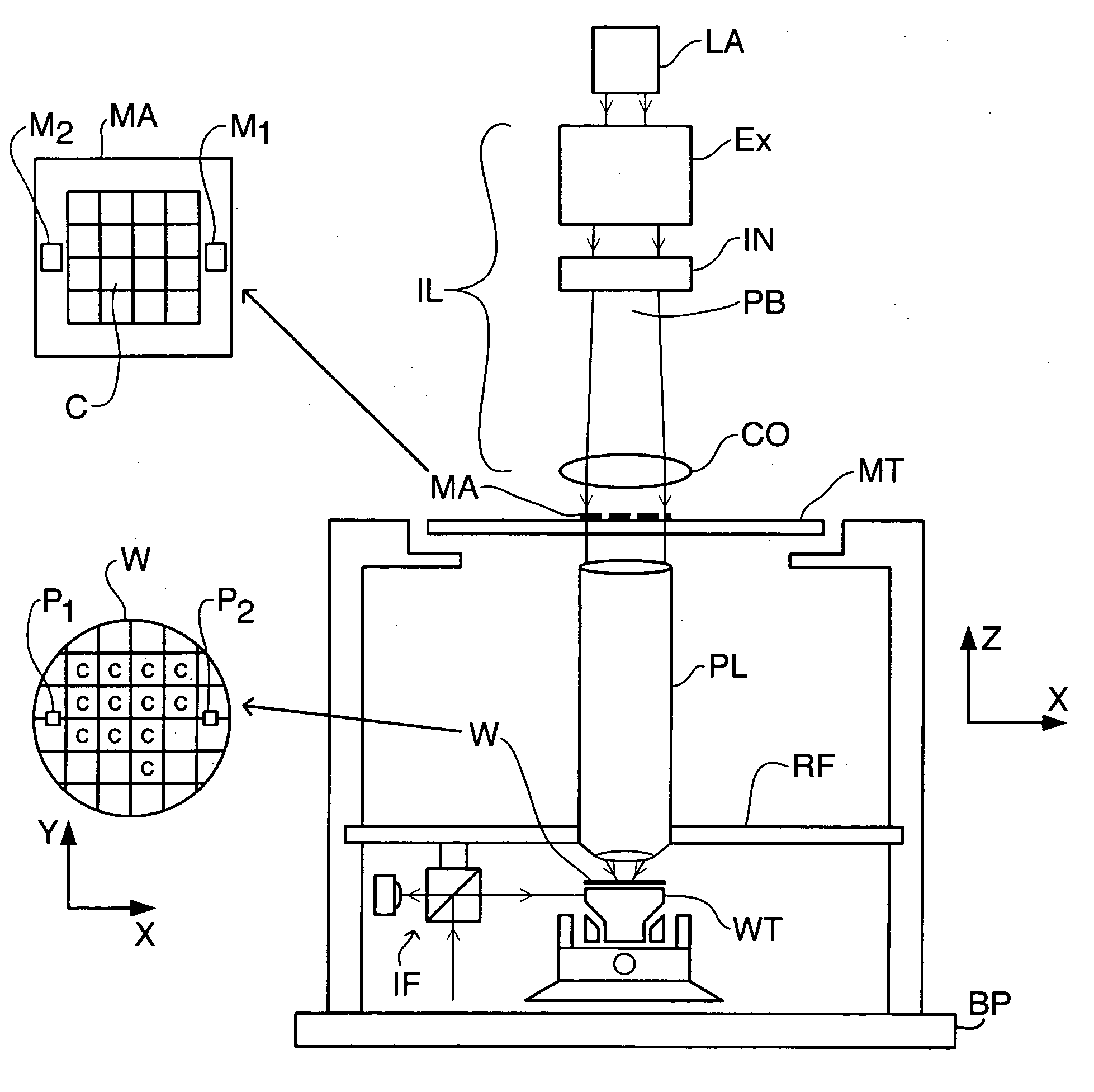
[0094]FIG. 1 schematically depicts a lithographic projection apparatus according to the invention. The apparatus comprises: [0095] a radiation system LA, IL for supplying a projection beam PB of radiation (e.g. UV or EUV radiation, x-rays, electrons or ions); [0096] a first object table (mask table) MT provided with a mask holder for holding a mask MA (e.g. a reticle), and connected to first positioning means for accurately positioning the mask with respect to item PL; [0097] a second object table (substrate table) WT provided with a substrate holder for holding a substrate W (e.g. a resist-coated silicon wafer), and connected to second positioning means for accurately positioning the substrate with respect to item PL; [0098] a projection system (“lens”) PL (e.g. a refractive or catadioptric system, a mirror group or an array of field deflectors) for imaging an irradiated portion of the mask MA onto a target portion C of the substrate W.

[0099] As here depicted, the apparatus is of ...

embodiment 2

[0133] The substrate stage, comprising substrate table WT, of a second embodiment of the invention, which may be the same as the first embodiment save as described below, is shown in FIG. 12.

[0134] In the second embodiment, the balance mass 406 takes the form of an open box with a flat interior base 407, forming a guide surface for the wafer table WT, and standing side walls 408 serving to raise the center of gravity of the balance mass 406. The substrate table WT includes a fine positioning mechanism 417 operating in 6 degrees of freedom for the substrate W and a so-called air-foot forming a substantially frictionless bearing allowing the substrate table WT to be moved over the guide surface 407.

[0135] Movement of the substrate table WT is effected by the coarse positioning mechanism. This includes X-beam 415 relative to which the substrate table WT is driven y an X-driver (not shown) which has at its ends sliders 411 which include the translators of Y-direction linear motors to ...

embodiment 3

[0138]FIG. 13 depicts the substrate stage, comprising substrate table WT, of a third embodiment of the invention, which may be the same as the first or second embodiments described above.

[0139] In the third embodiment, the balance mass is divided into two parts 506, 507. The first balance mass part 506 comprises a rectangular frame surrounding the subs ate table WT. Opposite sides of the first balance mass part 506 have mounted thereon the stator, e.g. the magnet track, of the Y-direction linear motors. The translators, e.g. coils, of the Y-direction linear motors, are mounted in sliders 511 at the ends of X-beam 515. The X-beam includes the stator of X-linear motor and the translator is mounted to the substrate table WT. Y- and Rz-reaction forces from the Y linear motor, which forms the coarse positioning mechanism together with the X-linear motor, are transmitted directly to the first balance mass part 506 and the Y-reaction forces are transmitted via thrust bearings (not shown)....


PUM

PropertyMeasurementUnit
distanceaaaaaaaaaa
wavelengthaaaaaaaaaa

Abstract

A balanced positioning apparatus comprises a balance mass which is supported so as to be moveable in the three degrees of freedom, such as X and Y translation and rotation about the Z-axis. Drive forces in these degrees of freedom act directly between the positioning body and the balance mass. Reaction forces arising from positioning movements result in corresponding movement of the balance mass and all reaction force are kept within the balanced positioning system. The balance mass may be a rectangular balance frame having the stators of two linear motors forming the uprights of an H-drive mounted on opposite sides. The cross-piece of the H-drive spans the frame and the positioned object is positioned within the central opening of the frame.

Description

[0001] This application is a continuation of U.S. application Ser. No. 09 / 739,097, filed Dec. 19, 2000, which claims priority from European application no. 99310371.2, filed Dec. 21, 1999 and European application No. 99310324.1, filed Dec. 21, 1999, the contents of each of which are incorporated herein by reference.FIELD OF THE INVENTION [0002] The present invention relates to balanced positioning systems, such as may be used to position a moveable object in at least three degrees of freedom. More particularly, the invention relates to the use of such a balanced positioning system in lithographic projection apparatus comprising: [0003] an illumination system for supplying a projection beam of radiation; [0004] a first object table for holding patterning means capable of patterning the projection beam according to a desired pattern; [0005] a second object table for holding a substrate; and [0006] a projection system for imaging the patterned beam onto a target portion of the substrat...

Claims


Application Information

Patent Timeline
Patent Type & Authority Applications(United States)
IPC IPC(8): G12B5/00G03F7/20H01L21/027
CPCG03F7/70716G03F7/709G03F7/70766H01L21/027
Inventor KWAN, YIM BUN PATRICKVAN DE WIEL, WILHELMUS JACOBUS THEODORUS PETRUS
Owner ASML NETHERLANDS BV
Why Eureka
Try Eureka