

Mud tank with pressurized compartment
- Summary
- Abstract
- Description
- Claims
- Application Information
AI Technical Summary
Benefits of technology
Problems solved by technology
Method used
Image

Examples
Embodiment Construction
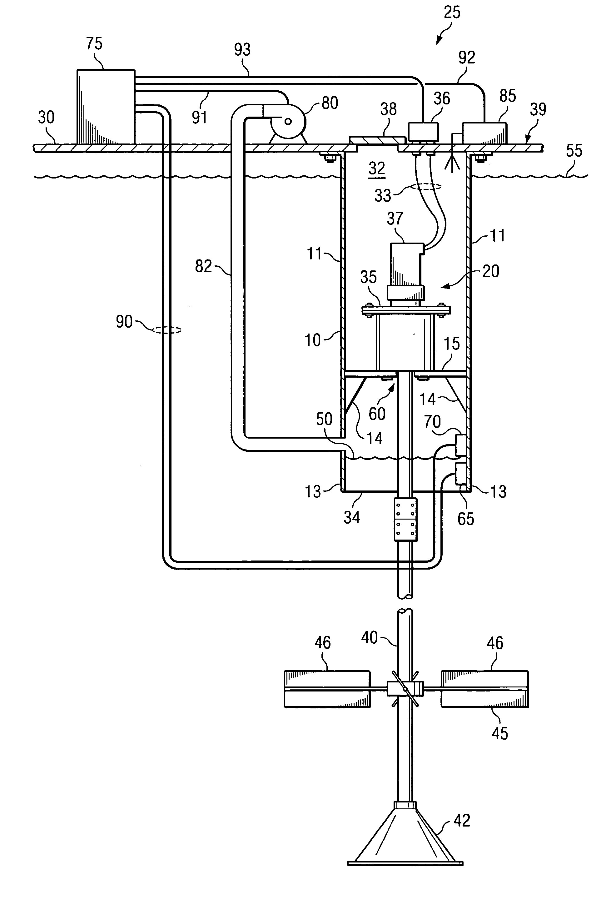
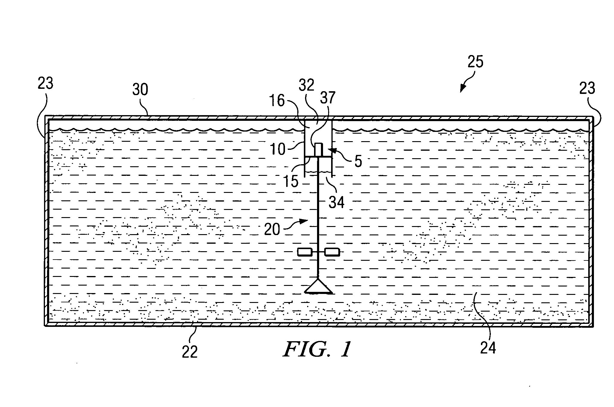
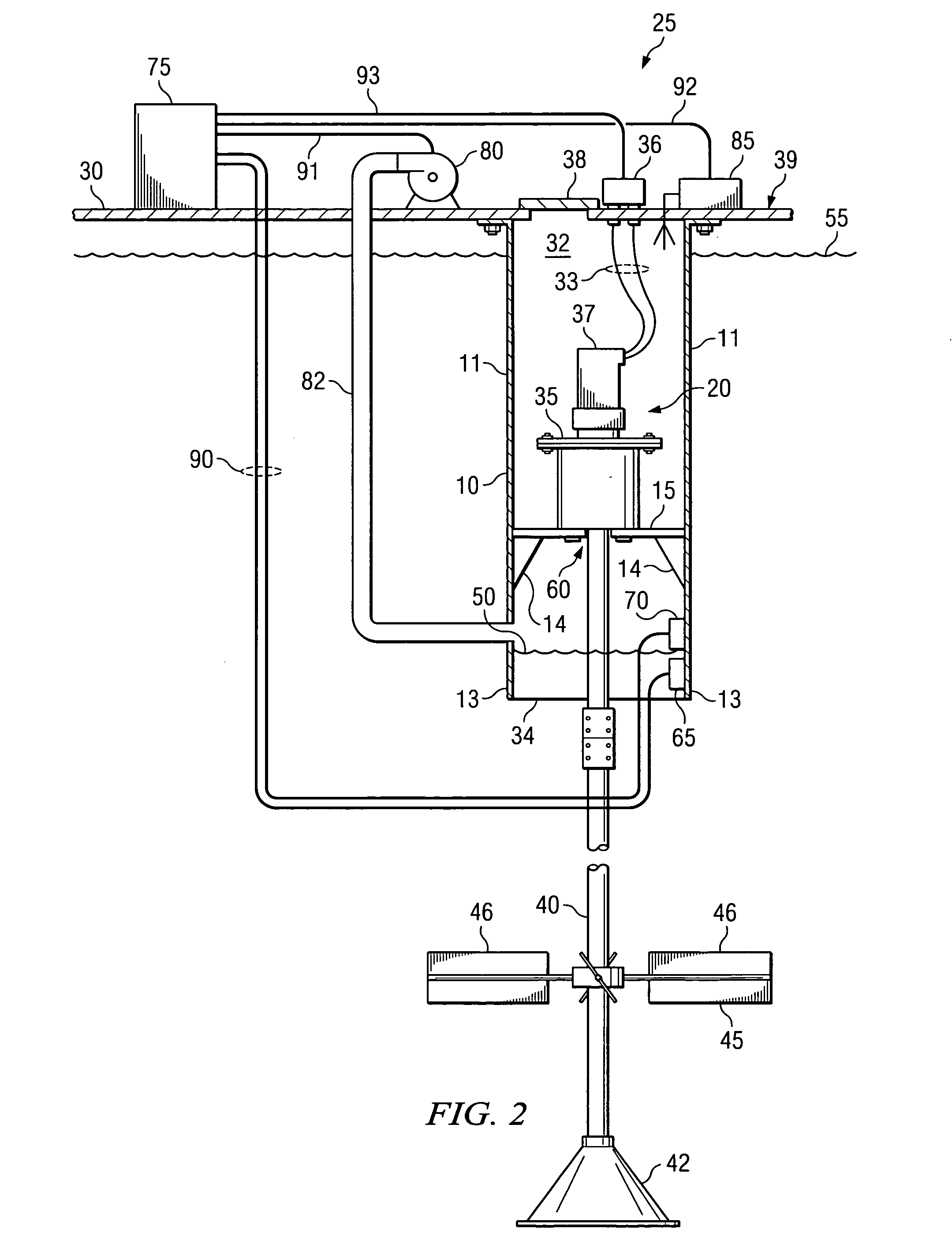
[0013] Preferred embodiments described herein include agitator apparatus for agitating a fluid or slurry contained within a tank or other enclosure. A vessel or chamber is disposed in the tank and includes a fluid-free compartment housing a motor. A shaft is connected to the motor and extends from the fluid-free compartment into the fluid. Blades and / or impellers are attached to the shaft at a position outside of the vessel for agitating the fluid in the tank.
[0014] The fluid-free compartment may be pressurized to maintain the fluid level in the vessel below the motor. This enables a non-submersible and thus, less costly, motor to be employed. A hatch or other accessway may be provided in the enclosure to allow access into the fluid-free compartment for servicing the agitator motor and related components.
[0015] In certain embodiments, the apparatus includes a controller and a level detector in the vessel for sensing the fluid level and sending a signal to the controller when the f...
PUM
 Abstract
Description
Claims
Application Information