
Apparatus and method for image processing, and computer product

Inactive Publication Date: 2005-09-22
RICOH KK
View PDF4 Cites 25 Cited by
  • Summary
  • Abstract
  • Description
  • Claims
  • Application Information

AI Technical Summary

Benefits of technology

[0014] An apparatus and method for image processing and computer product are described. In one embodiment, the image processing apparatus comprises a pseudo tone processor that performs a pseudo tone process by performing an area coverage modulation expression process with respect

Problems solved by technology

The method in JPEG adapted by most types of general-purpose software is a baseline method of JPEG, and its limitation is that the number of bits in the baseline method is 8 bits for each color.
However, sRGB has a narrow color gamut, requires gamut compression with respect to the input image from a scanner, and has poor color reproducibility.
On the other hand, sYCC and scRGB have substantially sufficient color gamut, but due to problems such as the size of the color gamut and quantization errors, it is necessary to express an image with a larger number of bits than in sRGB.
However, if low-order 2-bits are simply omitted, there is a problem in that a pseudo profile that is not visible in the case of 10-bit expression is visible in some images.
However, reduction in number of bits executed on the television is not executed by assuming subsequent lossy compression because a lossy compressor is not included.
If pseudo tone processing is performed with respect to an image to reduce the number of bits from 10 bits to 8 bits and then the JPEG processing is performed, there is a problem in that information for the low-order 2 bits subjected to the pseudo tone processing is almost lost, depending on the pseudo tone processing.
In the lossy compression, because the compressibility is increased by unsmoothing a quantization step for high frequency components, the loss occurs when the information for the low-order 2 bits is present just in the place where it is unsmooth in the quantization step.
(2) Further, there are few apparatuses that perform lossy compression such as JPEG after performing the pseudo tone processing.
However, the object of this technique is to reduce the storage capacity of the image memory (a memory used for a blocking unit 61 in FIG. 3), and not preservation of tone after the lossy compression, nor preservation of tone corresponding to 10 bits, which is the number of bits equal to or larger than the bits at the time of JPEG compression.
There is also a problem that when compressed data is transmitted to external equipment and displayed on a monitor a halftone image is visible (noticeability of error diffusion or dither basic tone).
The technique in (1) is a practical technique for displaying images on the television screen, but the number of bits is not reduced by assuming the lossy compression, because the lossy compressor is not provided in the stage after reduction of number of bits.
Therefore, the problem that a halftone image appears when compressed data is transmitted to external equipment and displayed on a monitor, still persists.

Method used


Image

  • Apparatus and method for image processing, and computer product
  • Apparatus and method for image processing, and computer product
  • Apparatus and method for image processing, and computer product

Examples


first embodiment

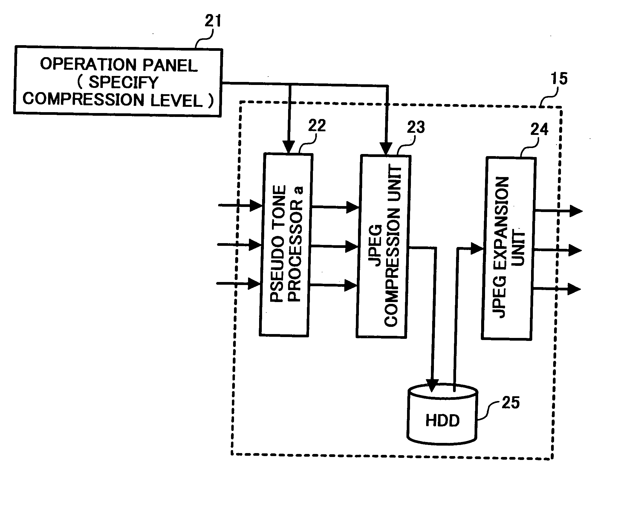
[0072]FIG. 11 is a functional block diagram of the image processing apparatus 15 according to a The image processing apparatus in this embodiment has a function for specifying the compression level via an operation panel 21. More specifically, the scaling factor in a JPEG compression unit 23 can be changed, and hence, the compression level can be changed. In comparison with FIG. 3, the configuration is such that the scaling factor setting unit 67 becomes variable.

[0073]FIGS. 12A and 12B illustrate a difference in the average density preservability according to the compression level of the image processing apparatus. When the compression level of the image processing apparatus changes, the average density preservability also changes. In the case of a low compressibility (small quantization), the average density preservability from the intermediate frequency to the high frequency improves, and in the case of a high compressibility (large quantization), the average density preservabil...

third embodiment

[0095]FIG. 18 is a functional block diagram of an image processing apparatus according to a The image processing apparatus 15 in this embodiment includes an edge extractor 44 that generates a signal capable of responding by an edge of an image, and an image synthesis unit 47 that synthesizes an image after the JPEG expansion. As shown in FIGS. 6A and 6B, in an image after compression and expansion, high frequency components attenuate and edge components are weakened. Therefore, the weakened edge components (ideally, a difference between before and after the compression, but such a high precision is not required) are generated from the signal before the JPEG compression, stored, and subjected to image synthesis, to restore the sharpness of the edge. In FIG. 18, the edge extractor 44 uses a signal before a pseudo tone processor a 41, but a signal immediately before the JPEG compression may be used therefor.

[0096] For example, consider that the number of bits before the pseudo tone pr...


PUM


Abstract

In an image processing apparatus, a pseudo tone processor performs a pseudo tone process by performing an area coverage modulation expression process with respect to M-bit image data, to thereby convert the M-bit image data into N-bit image data, where N is smaller than M. A lossy compressor performs lossy compression with respect to the N-bit image data, by suppressing fluctuations in a pseudo tone processing frequency within a certain range.

Description

[0001] The present application claims priority to and incorporates by reference the entire contents of Japanese priority documents, 2004-079291, filed in Japan on Mar. 18, 2004, and 2004-322716 filed in Japan on Nov. 5, 2004. BACKGROUND OF THE INVENTION [0002] 1. Field of the Invention [0003] The present invention relates to an apparatus and a method for image processing, and a computer product in which a tone corresponding to bits in an image in preserved, and mean value preservability and the visual performance can be substantially obtained. [0004] 2. Description of the Related Art [0005] Conventionally, in a color copying machine having an image storage unit such as a hard disk, an image read by a scanner is stored in the hard disk, and transmitted to external equipment. Considering storage capacity and transmission speed, images are generally compressed before storing or transmitting. Another conventional apparatus is one in which lossy compression is employed, as represented by...

Claims


Application Information

Patent Timeline
IPC IPC(8): G06T5/00G06K9/36G06T9/00H04N1/387H04N1/40H04N1/41H04N1/64
CPCH04N1/646H04N19/124H04N19/60H04N19/176
Inventor MIYAGI, NORIKOINAMOTO, HIROHISA
Owner RICOH KK
Features
  • Generate Ideas
  • Intellectual Property
  • Life Sciences
  • Materials
  • Tech Scout
  • Unparalleled Data Quality
  • Higher Quality Content
  • 60% Fewer Hallucinations
Learn More