System and method for detecting and identifying an analyte

a technology of analyte detection and identification method, applied in the field of automatic testing, can solve the problems of difficult or impractical placement of testing equipment, difficult or impractical retrieval of samples, and inability to adapt to a number of applications

Active Publication Date: 2005-09-22
QUANTASPEC
View PDF18 Cites 138 Cited by
  • Summary
  • Abstract
  • Description
  • Claims
  • Application Information

AI Technical Summary

Problems solved by technology

However, equipment-centric methods are generally not suited to a number of applications, especially applications where it is, among other things: (1) difficult or impractical to place testing equipment at the location of the analyte to be tested; (2) difficult or impractical to retrieve a sample of the analyte from a particular location and test the sample at a location away from the location where the sample was obtained and/or (3) dangerous to place testing equipment at, and retrieve a sample from, the location where the analyte may be present.
However, conventional embodiments of these detectors have one or more drawbacks or undesirable limitations under certain circumstances.
Unfortunately, the atmosphere strongly absorbs infrared light severely limiting the range and sensitivity of such systems.
Furthermore, the Raman shift is a very inefficient process and, therefore, has a severely limited sensitivity.
Therefore this approach is limited in the type of analytes it can detect.
In addition, it suffers from drawbacks in sensitivity and range because the ultraviolet light required is absorbed strongly by the atmosphere.
Furthermore, photoluminescence is not very selective.
FTIR sensors suffer from several operational drawbacks when attempting to use such devices as remote sensors.
First, FTIR sensors rely on an interferometer that generally requires the instrument to be stationary while acquiring measurement data.
This limits the operational flexibility and mobility of FTIR sensors.
Therefore, FTIR sensors are not suitable for detection of analytes on the move.
In addition to these flexibility and mobility issues, the infrared light sources used in FTIR detectors typically lack spectral intensity, thereby limiting the sensitivity, and range of the sensors.
FLIR detection is generally limited to sensing and identifying simple analytes, such ...

Method used


Image

  • System and method for detecting and identifying an analyte
  • System and method for detecting and identifying an analyte
  • System and method for detecting and identifying an analyte

Examples


Embodiment Construction

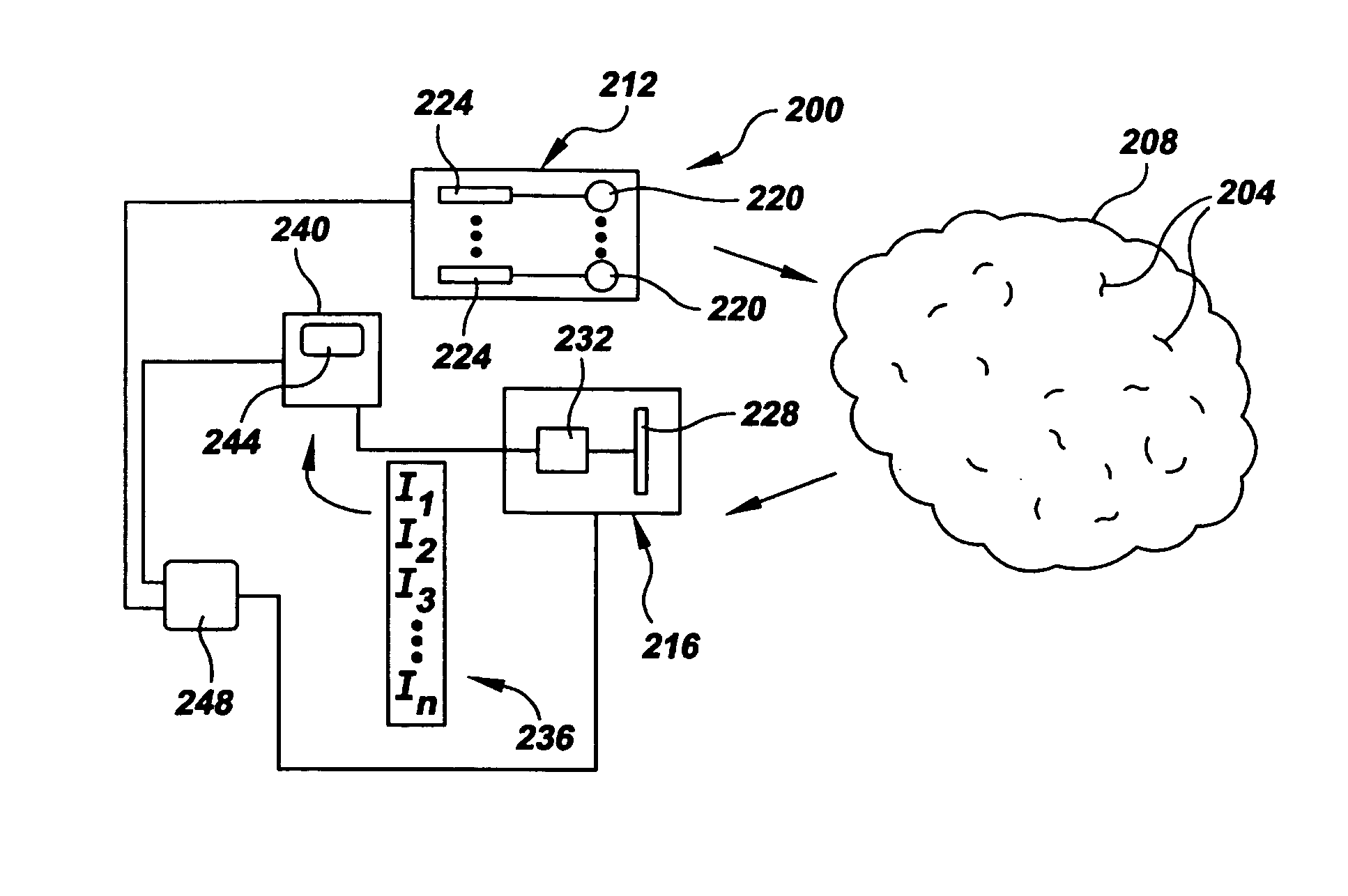
[0044] Referring now to FIG. 2, there is shown in accordance with the present invention an analyte detecting and identifying system, or “sensor,” which is generally denoted by the numeral 200. In general, sensor 200 is operatively configured to detect the presence of and / or identify one or more analytes 204 of interest in a sample region 208 by directing spectral energy into the region and sensing this energy, or lack thereof, after it passes out of the region. As is well known, due to their chemical structure different analytes have different spectral absorption characteristics across various wavelengths, much like different human finger prints have different patterns of ridges and valleys. These spectral absorption characteristics, being unique to the analyte, allow analytes to be detected and identified.

[0045] Identifying an analyte, such as analyte 204, generally involves chemical identification and / or biological identification. In chemical identification, an analyte may be ide...


PUM

PropertyMeasurementUnit
Lengthaaaaaaaaaa
Sizeaaaaaaaaaa
Energyaaaaaaaaaa

Abstract

A sensor (200, 900) comprising an illuminator (212, 500, 804, 832, 858, 904), a receiver (216, 400, 420, 460, 480, 808, 836, 862, 924) and an analyzer (240) for detecting and identifying an analyte having a characteristic absorption band that is present in a sample region (208, 812, 824, 874, 922). The illuminator includes an illumination source (220) for illuminating the sample region with spectral energy across at least a portion of the characteristic absorption band. The receiver includes a detector (228, 404, 424, 460, 484, 866, 928) for sensing predetermined portions of the spectral energy band and for creating a sample spectral data vector (236). The analyzer uses the spectral data vector and known characteristic data to detect and identify the analyte.

Description

RELATED APPLICATION DATA [0001] This application claims the benefit of priority of U.S. Provisional Patent Application Ser. No. 60 / 555,166, filed Mar. 22, 2004, and titled “Method And Means For Remote Particle Sensing” and U.S. Provisional Patent Application Ser. No. 60 / 599,692, filed Aug. 6, 2004, and titled “Method And Apparatus For Remote Sensing”, each of which is incorporated by reference herein in its entirety.FIELD OF THE INVENTION [0002] The present invention generally relates to the field of automated testing. In particular, the present invention is directed to a system and method for detecting and identifying an analyte. BACKGROUND OF THE INVENTION [0003] The ability to sense and identify matter using automated equipment has been known for many years and is important to the general field of testing that has application in the physical sciences and across a broad spectrum of modern pursuits that rely on the physical sciences, including manufacturing, medicine, government re...

Claims


Application Information

Patent Timeline
IPC IPC(8): B32B5/02C12Q1/04G01N21/29G01N21/31G01N21/35G01N21/41G01N21/47G01N21/53
CPCC12Q1/04G01N21/31G01N21/3504G01N21/53G01N2021/1793G01N2021/4728G01N2021/3166G01N2021/3513G01N2021/4707G01N2021/4709G01N2021/3137
Inventor PUZEY, KENNETH A.
Owner QUANTASPEC
Why Eureka
Try Eureka