High flow air filtration system

a high-flow air and filtration system technology, applied in the direction of filtration separation, combustion-air/fuel-air treatment, separation process, etc., can solve the problems of air turbulence, engine efficiency, horsepower, torque and fuel economy decline,

Inactive Publication Date: 2005-09-29
ADVANCED FLOW ENG
View PDF14 Cites 15 Cited by
  • Summary
  • Abstract
  • Description
  • Claims
  • Application Information

AI Technical Summary

Benefits of technology

[0016] In still a further aspect of the present invention, a method of filtering airborne particulates from ambient air includes steps of: optimally sizing an annular aperture so that a required airflow is achieved when passing ambient air through the annular aperture; and spacing pleats of a pleated material of a filter media at no less than a minimum distance required for achieving maximal net filtration area when passing the ambient air through the filter media.

Problems solved by technology

The features and filter design choices that lead to improvements in one of these parameters (e.g., particle entrapment, airflow permeability, and filter lifetime) can lead to declines in the other performance parameters.
This tends to decrease engine efficiency, horsepower, torque, and fuel economy.
However, such designs may foster air turbulence at the filter intake, which is an undesirable quality that ultimately impairs airflow.
When air eddies cause influent air to bypass regions for the filter media near these abrupt transitions, the effective area available for filtration is reduced.

Method used


Image

  • High flow air filtration system
  • High flow air filtration system
  • High flow air filtration system

Examples


Embodiment Construction

[0027] The following detailed description is of the best currently contemplated modes of carrying out the invention. The description is not to be taken in a limiting sense, but is made merely for the purpose of illustrating the general principles of the invention, since the scope of the invention is best defined by the appended claims.

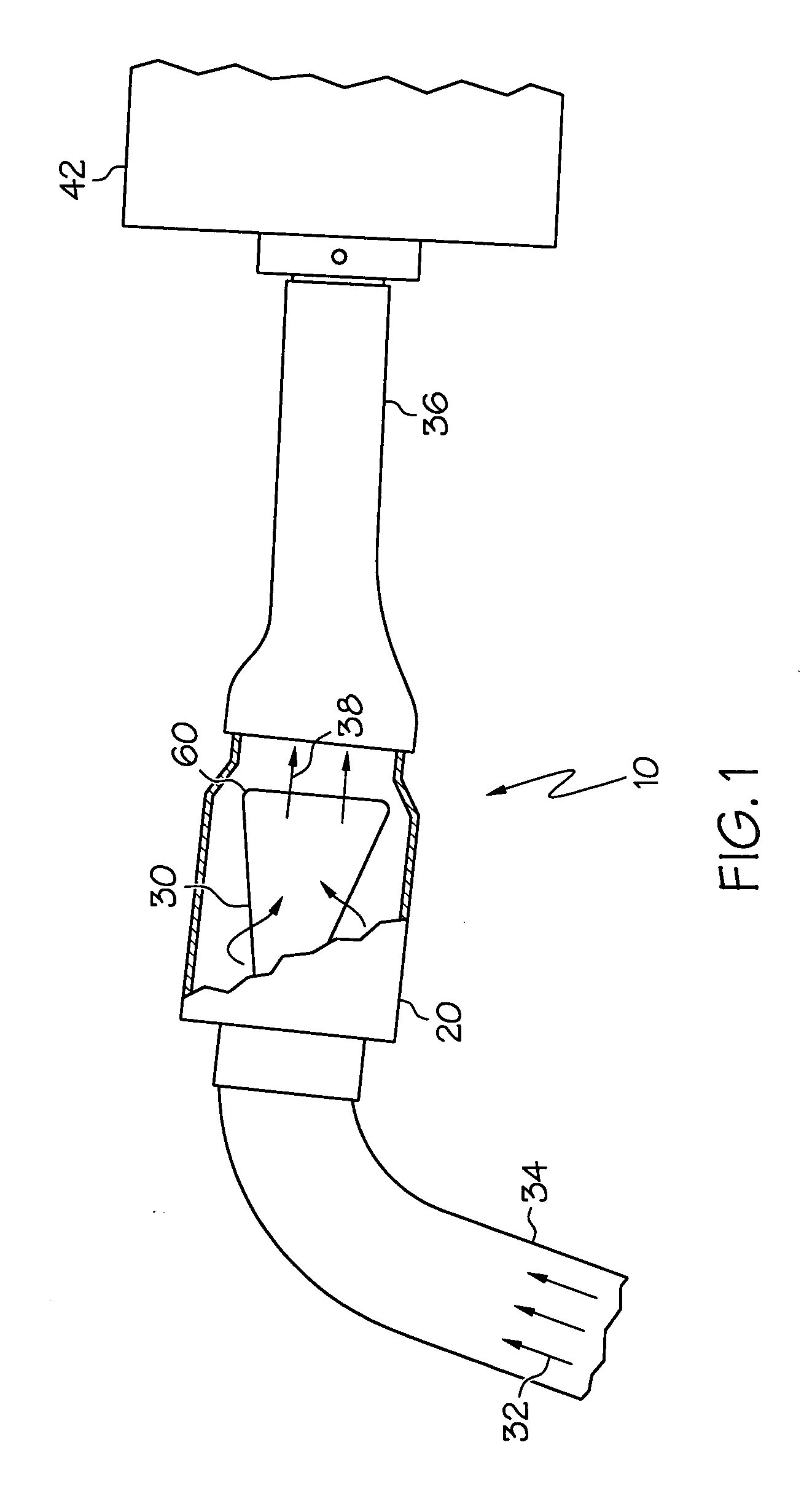
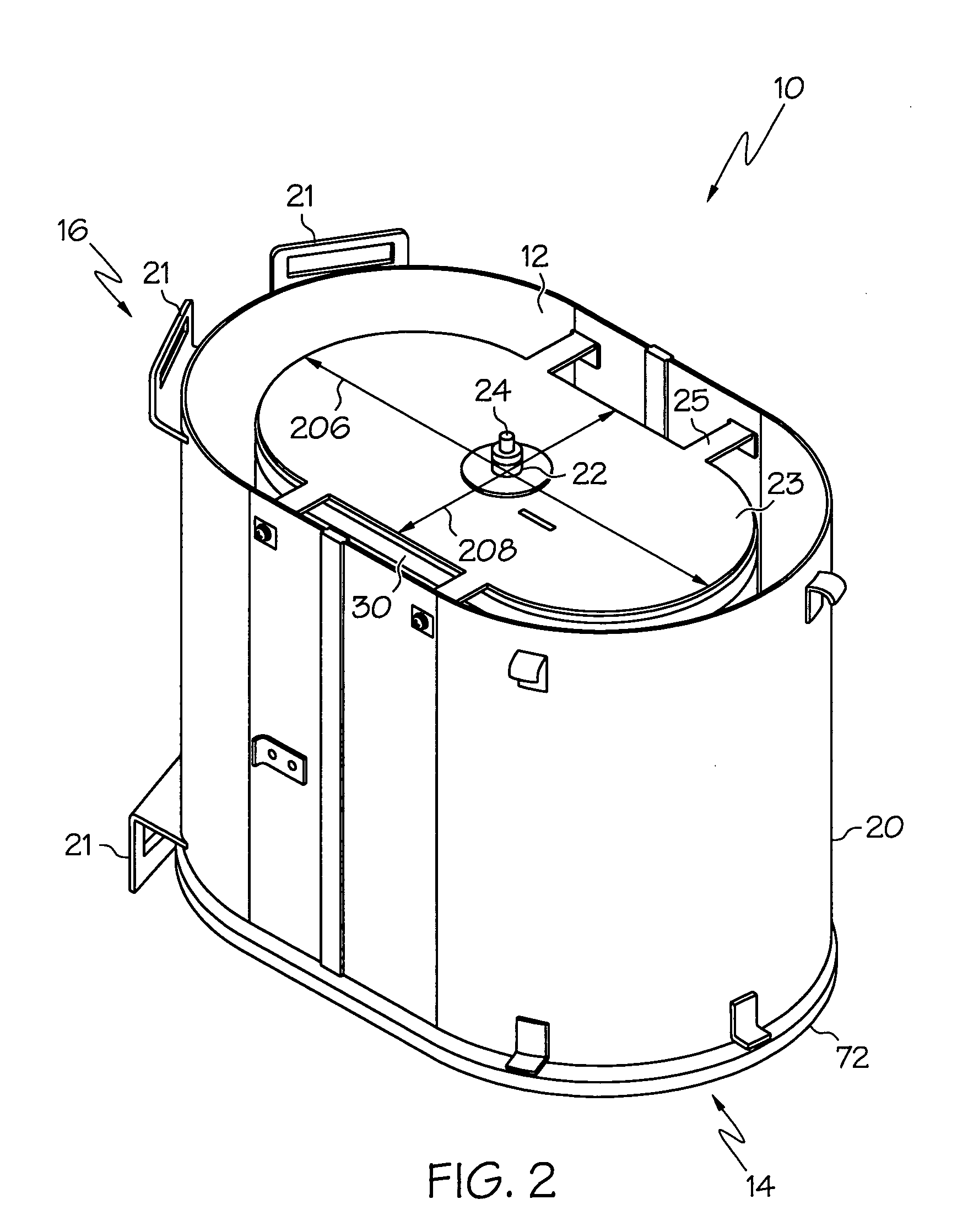
[0028] Broadly, the present invention provides an air filtration system for the intake portion of an internal combustion engine (such as found in an automobile and, in particular, Ford F-Series pickup trucks with a V8-6.0 L turbo diesel engine).

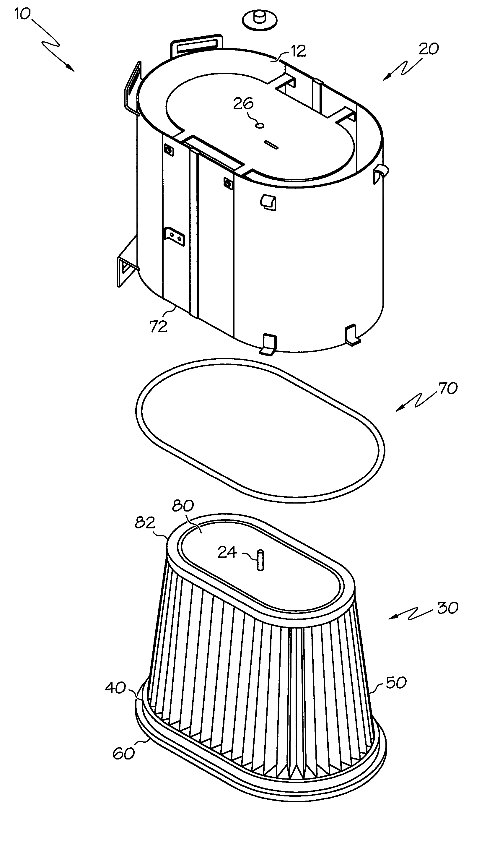
[0029] An embodiment of the present invention may be distinguished from the prior art in its overall configuration, in which a pleated filter media of substantially conical form is placed with its air permeable wall divergent relative to the direction of airflow, with the narrow end of the conical form upstream and closed off by a disk-like base so that air passes from the outside of the cone to the inside and...


PUM

PropertyMeasurementUnit
thicknessaaaaaaaaaa
distanceaaaaaaaaaa
sizeaaaaaaaaaa

Abstract

An apparatus for filtering air includes a filter housing having an end plate and an annular aperture defining the size and shape of the end plate; and a filter element having a lip at an open end and a base at a closed end. The lip seals the filter element to the filter housing and to an unmodified, stock air intake of a vehicle. The filter media comprises pleated natural fiber fabric supported between two structural mesh layers. The base has a mounting post attached to the base that fits into a mounting hole in the end plate of the filter housing to hold the filter element in the housing. The base matches the size and shape of the end plate. The base and annular aperture are sized to optimize the filter media and pleat spacing for achieving a required airflow and maximal effective area for filtration.

Description

CROSS-REFERENCE TO RELATED APPLICATIONS [0001] This application claims the benefit of U.S. Provisional Patent Application No. 60 / 556,171, filed on Mar. 24, 2004.BACKGROUND OF THE INVENTION [0002] This invention relates to high performance air filtration systems, in particular, to high performance air filtration systems, such as for use within the Ford F-Series pickup trucks with a V8-6.0 L turbo diesel engine. [0003] The function of an air intake filter is to remove the particulate matter from the intake air, so that clean air is provided to the engine. The intake air stream flows from the influent, or “dirty,” side of the filter to the effluent, or “clean,” side of the filter, with the air filter extracting the unwanted particles via one or more filter media layers. Filter media are selected to trap particles exceeding a particular size, while remaining substantially permeable to airflow over an expected filter lifetime. [0004] The features and filter design choices that lead to im...

Claims


Application Information

Patent Timeline
Patent Type & Authority Applications(United States)
IPC IPC(8): B01D46/00B01D46/24B01D46/52F02M35/02
CPCB01D46/0005B01D46/001B01D46/2403F02M35/0203B01D2271/02B01D2275/10F02M35/02B01D46/521
Inventor MIYAGISHIMA, STUART T.NIAKAN, SHAHRIAR NICKZAMBRANO, SAUL DANIELBARRON, CHRISTOPHER M.
Owner ADVANCED FLOW ENG
Why Eureka
Try Eureka