
Gas chromatograph mass spectrometer

a mass spectrometer and gas chromatograph technology, applied in the direction of instruments, particle separator tube details, separation processes, etc., can solve the problems of time-consuming, difficult to prepare two sets of interfaces, and high cost, and achieve good vacuum

Active Publication Date: 2005-09-29
SHIMADZU CORP
View PDF3 Cites 14 Cited by
  • Summary
  • Abstract
  • Description
  • Claims
  • Application Information

AI Technical Summary

Benefits of technology

The present invention provides a gas chromatograph mass spectrometer that can use a single column or multiple columns without changing the whole interface. The interface includes a heat-retention block, a single-hole ferrule, a plural-hole ferrule, an adapter, a single-column nut, and a plural-column nut. When using a single column, the heat-retention block and ferrule are used, while when using multiple columns, the heat-retention block, adapter, ferrule, and nuts are used. This allows for easy switching between the two modes and ensures a high vacuum in the mass spectrometer part. The invention provides a cost-effective solution for upgrading the gas chromatograph mass spectrometer.

Problems solved by technology

Thus an exchange of columns is often necessary, which is one of troublesome operations of a GC / MS.
There is a problem in this case.
But the changing operation of the interface 20 needs a lot of care and is time-consuming.
Preparing two sets of interfaces is also financially disadvantageous.

Method used


Image

  • Gas chromatograph mass spectrometer
  • Gas chromatograph mass spectrometer
  • Gas chromatograph mass spectrometer

Examples


Embodiment Construction

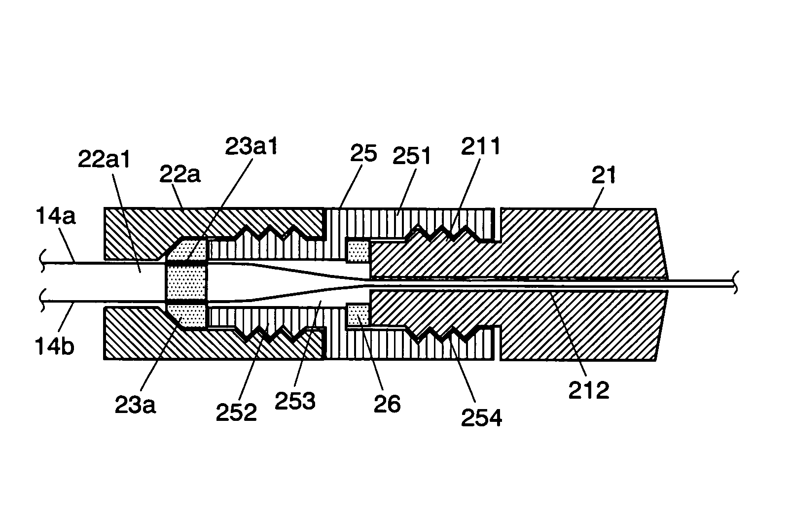
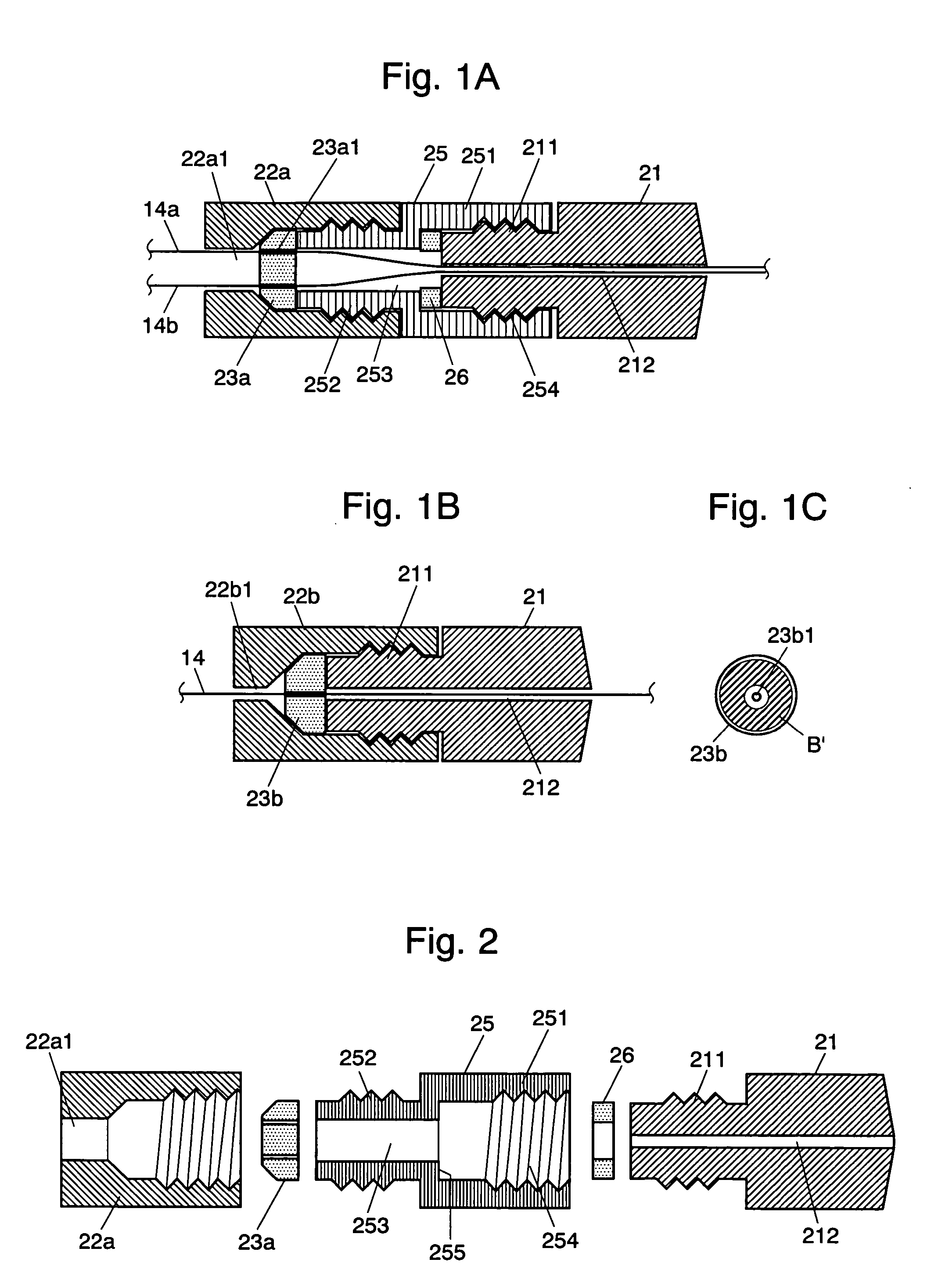
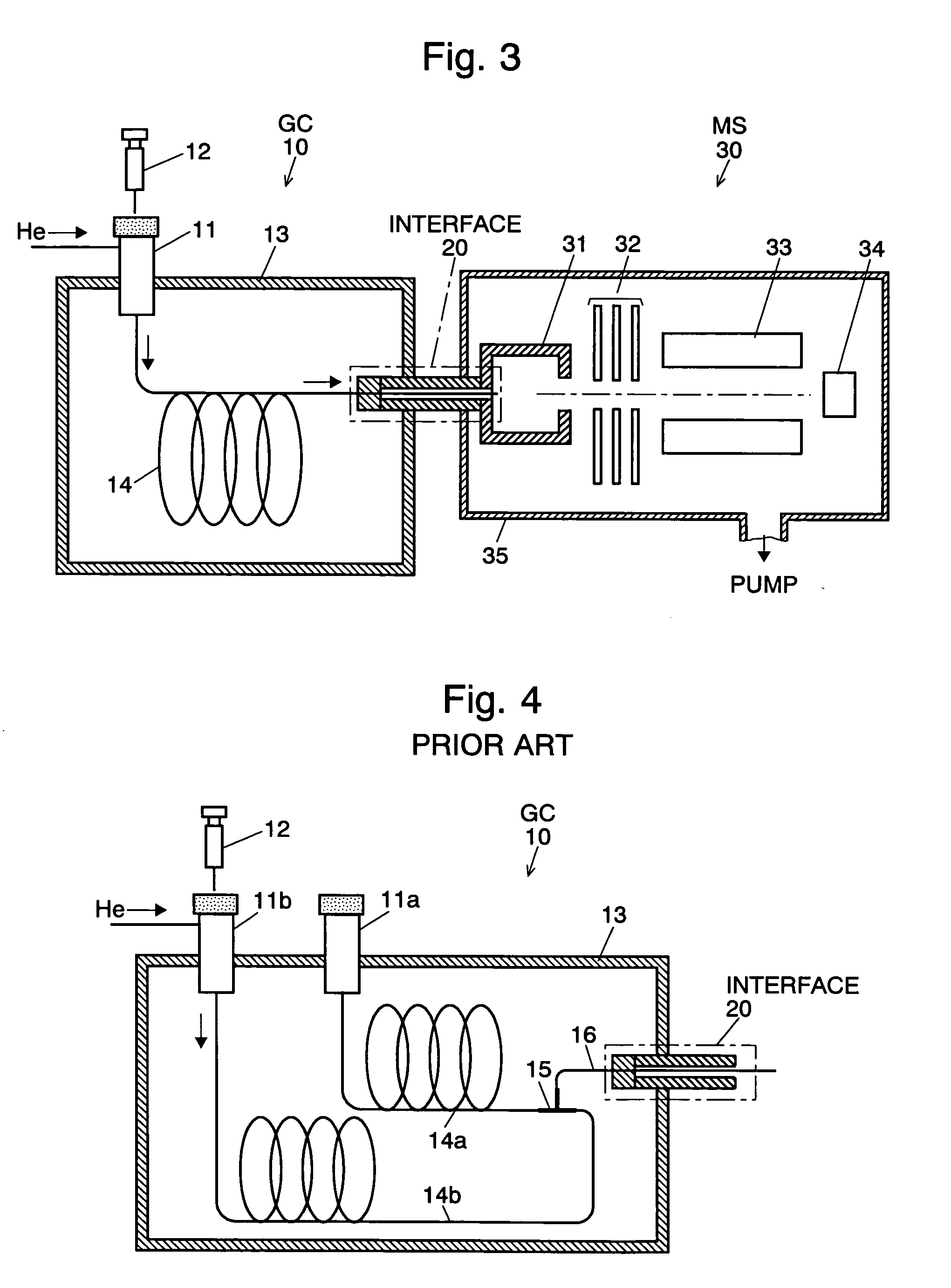
[0027] A GC / MS embodying the present invention is described referring to the attached drawings. The principal structure of the GC / MS of the present embodiment is as shown in FIG. 3 and as described above, whereas the GC / MS of the present embodiment has a characteristic structure in the interface 20. The structure of the interface 20 of the GC / MS of the present embodiment is described referring to FIGS. 1A, 1B, 1C and 2.

[0028]FIG. 1A shows the interface 20 of the present embodiment when used with two columns, and FIG. 1B shows the same when used with a single column. FIG. 2 shows the components of the interface 20 as used with two columns (FIG. 1A) in a separated state. The elements as described above are assigned the same numbers as those in said figures. The diameter of the hole 212 of the heat-retention block 21 is the same as that shown in FIG. 4, so that two columns 14a, 14b can pass the hole 212 in a close position. When the interface 20 is used with a single column 14, as sho...


PUM

PropertyMeasurementUnit
specific mass to charge ratioaaaaaaaaaa
diameteraaaaaaaaaa
Gas chromatograph mass spectrometersaaaaaaaaaa

Abstract

An interface placed between a gas chromatograph part and a mass spectrometer part of a gas chromatograph mass spectrometer (GC / MS) for allowing a column or two columns to pass air-tightly from the gas chromatograph part to the mass spectrometer part includes: a heat-retention block having a small-diameter hole for allowing two columns to pass therethrough; a single-hole ferrule having a small-diameter hole for allowing a single column to pass therethrough; a two-hole ferrule having two small-diameter holes for allowing two columns to respectively pass therethrough; an adapter placed between the heat-retention block and the below-described two-column nut, and including a long large-diameter opening for allowing two columns passing through the two-hole ferrule to converge on the small-diameter hole of the heat-retention block without excessively bending two columns; a single-column nut for pressing the single-hole ferrule to the heat-retention block; and a two-column nut for pressing the two-hole ferrule to the adapter. When a single column is used in the gas chromatograph part, the heat-retention block, the single-hole ferrule and the single-column nut are used. In this case, the heat-retention block and the ferrule contact with a large area, which ensures a high air-tightness. When two columns are used, the heat-retention block, the adapter, the two-hole ferrule and the two-column nut are used. The two columns passing through two small-diameter holes respectively of the two-hole ferrule can converge on the small-diameter hole of the heat-retention block without being excessively bent or forced. The change of the two modes is rather easy, and the difference in the two cases is the change of the ferrules and nuts, and insertion of the adapter, which are all relatively inexpensive. The expensive heat-retention block is commonly used.

Description

[0001] The present invention relates to a gas chromatograph mass spectrometer in which a mass spectrometer is used as a detector of a gas chromatograph, and specifically to an interface which connects the gas chromatograph part and the mass spectrometer part. BACKGROUND OF THE INVENTION [0002] Gas chromatograph mass spectrometers (GC / MS) are nowadays widely used in qualitative as well as quantitative analyses of various sample substances. A conventional gas chromatograph mass spectrometer is described referring to FIG. 3. The Unexamined Japanese Patent Publication Nos. H10(1998)-283982 and 2001-208740 disclose such gas chromatograph mass spectrometers. [0003] In a gas chromatograph (GC) part 10, a sample atomizer 11 is provided at the entrance of a capillary column 14, which is enclosed by a column oven 13. A carrier gas flows through the sample atomizer 11 and the column 14 at a constant rate. When a liquid sample is injected by an injector 12 into the sample atomizer 11, the sampl...

Claims


Application Information

Patent Timeline
Patent Type & Authority Applications(United States)
IPC IPC(8): G01N27/62G01N30/60G01N30/72H01J49/04
CPCG01N30/72G01N30/7206G01N2030/6013G01N2030/7226H01J49/0422G01N30/466G01N2030/3038
Inventor SHIMOMURA, MANABU
Owner SHIMADZU CORP
Learn More