Fuel supply system of internal combustion engine

Active Publication Date: 2005-09-29
DENSO CORP
View PDF10 Cites 36 Cited by
  • Summary
  • Abstract
  • Description
  • Claims
  • Application Information

AI Technical Summary

Benefits of technology

[0014] In the above structure, the valve closing control for holding the electromagnetic valve at the closed state is performed when the crank angle cannot be sensed before crank angle determination is completed during an engine starting period. Thus, the fuel supplied from the low-pressure pump can be pressurized and supplied to the fuel injection valve side by the high-pressure pump

Problems solved by technology

Therefore, operation noise (collision noise) is generated by collision between a valve member and a valve seat or collision between a movable portion and a stopper portion accompanying the opening and closing of the electromagnetic valve.
In such a case, there is a possibility that the operation sound of the electro

Method used


Image

  • Fuel supply system of internal combustion engine
  • Fuel supply system of internal combustion engine
  • Fuel supply system of internal combustion engine

Examples


first embodiment

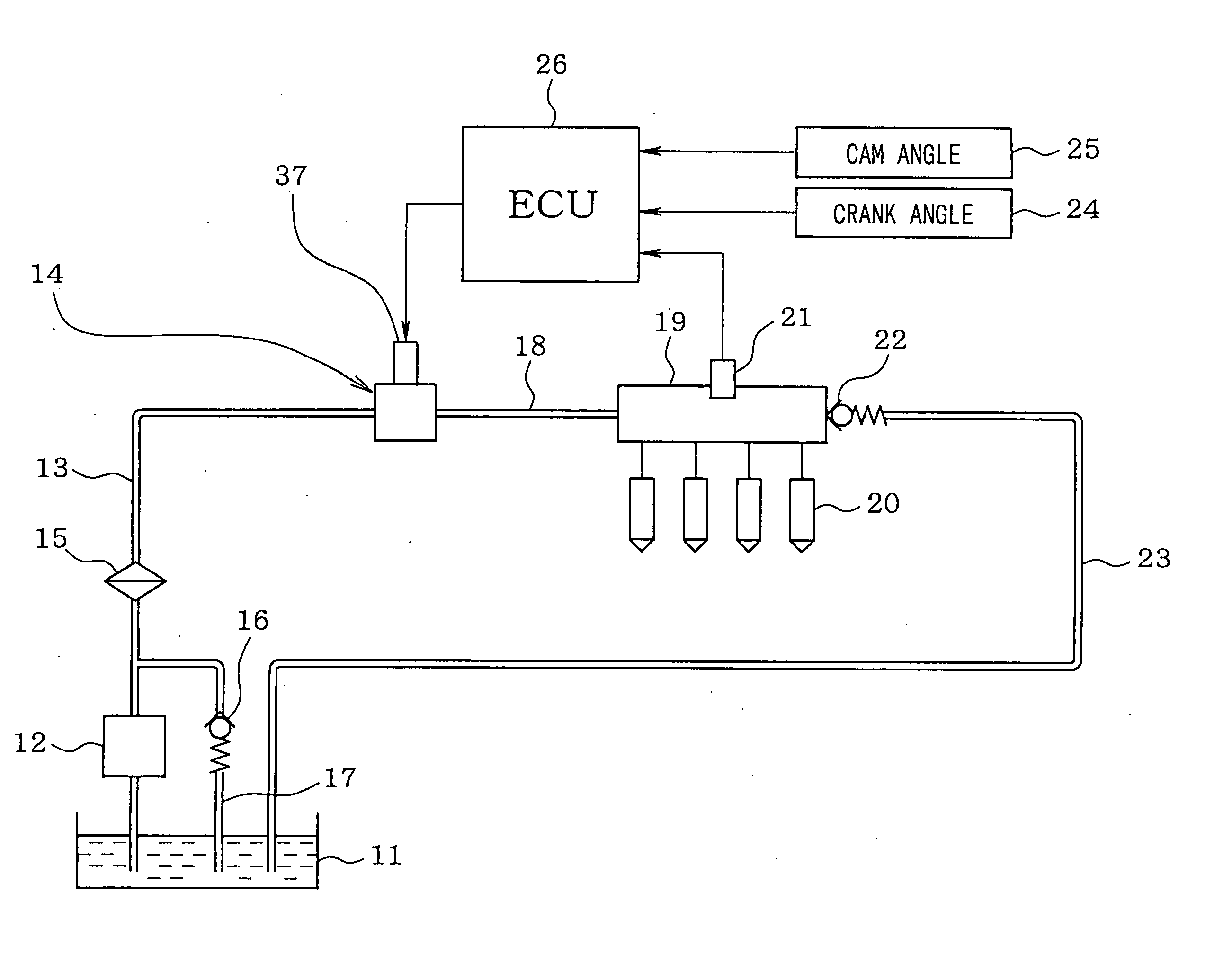
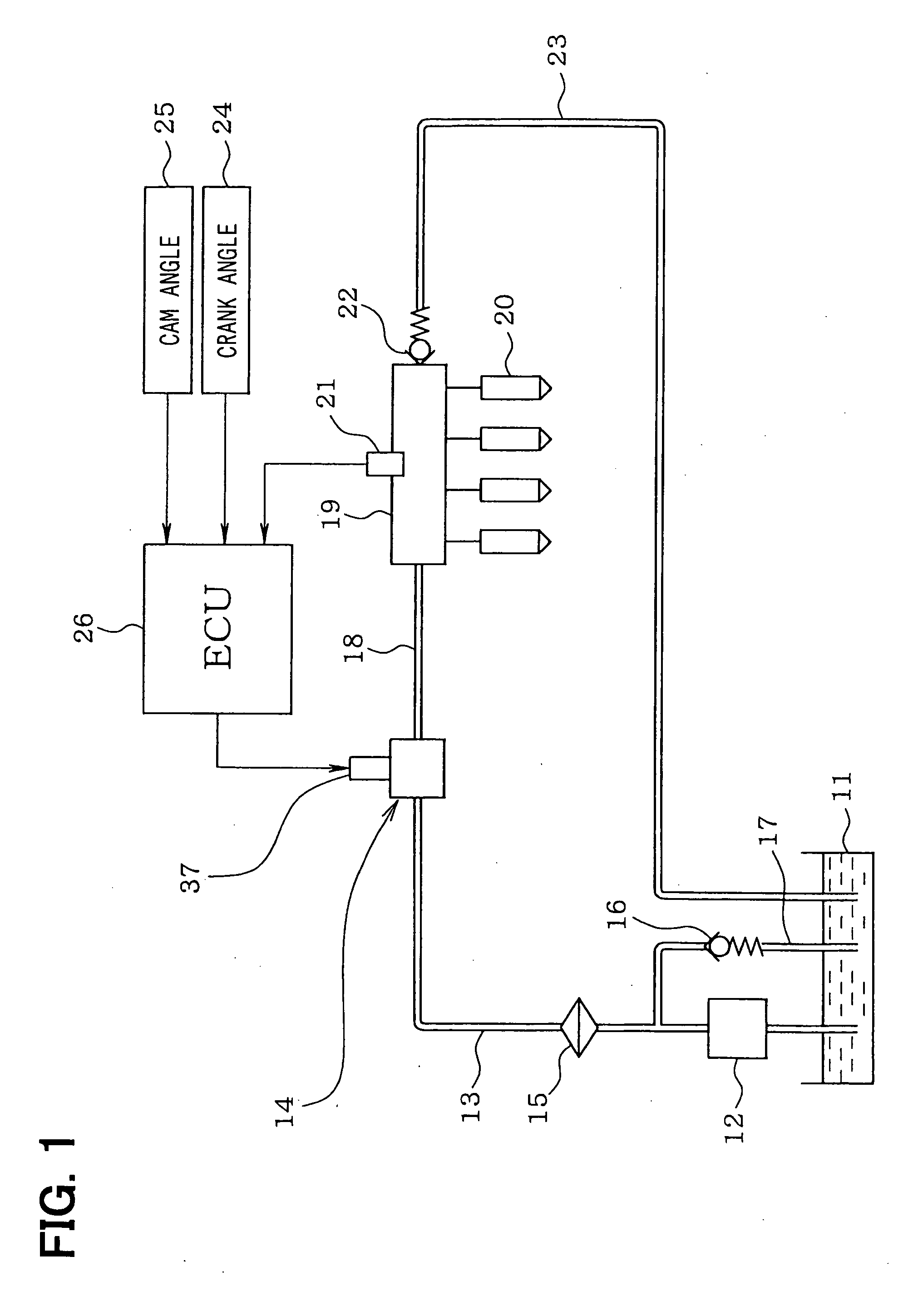
[0030] Referring to FIG. 1, a fuel supply system of a direct injection type gasoline engine (an internal combustion engine) according to a first embodiment of the present invention is illustrated. An electric low-pressure pump 12 for drawing fuel is disposed in a fuel tank 11 storing the fuel. The low-pressure pump 12 is driven by an electric motor using a battery as a power source. The fuel discharged from the low-pressure pump 12 is supplied to a mechanical high-pressure pump 14 through a low-pressure side fuel pipe 13. A fuel filter 15 is disposed in the low-pressure side fuel pipe 13. A low-pressure regulator 16 is connected to the low-pressure side fuel pipe 13. The low-pressure regulator 16 regulates a discharge pressure of the low-pressure pump 12 (a fuel supply pressure to the high-pressure pump 14) to a predetermined pressure. Excess fuel causing a pressure higher than the predetermined pressure is returned into the fuel tank 11 through a fuel return pipe 17.

[0031] The fue...

second embodiment

[0048] Next, a fuel supply system according to a second embodiment of the present invention will be explained based on FIG. 6.

[0049] As explained above, the high-pressure pump 14 suctions the fuel through the secondary suction passage 34 during the valve closing control of the electromagnetic valve 37. However, the fuel injection quantity of the engine decreases when the engine is in a low rotation speed operation state (for instance, the idling operation state), in which the valve closing control is performed.

[0050] Therefore, in the second embodiment, a restriction passage portion 41, of which a passage sectional area is narrowed, is formed in the secondary suction passage 34 of the high-pressure pump 14 on an upstream side or a downstream side of the check valve 35 as shown in FIG. 6. The passage sectional area of the restriction passage portion 41 is larger than an area capable of suctioning the fuel quantity corresponding to the fuel injection quantity in the idling operation...

third embodiment

[0052] Next, a fuel supply system according to a third embodiment of the present invention will be explained based on FIG. 7.

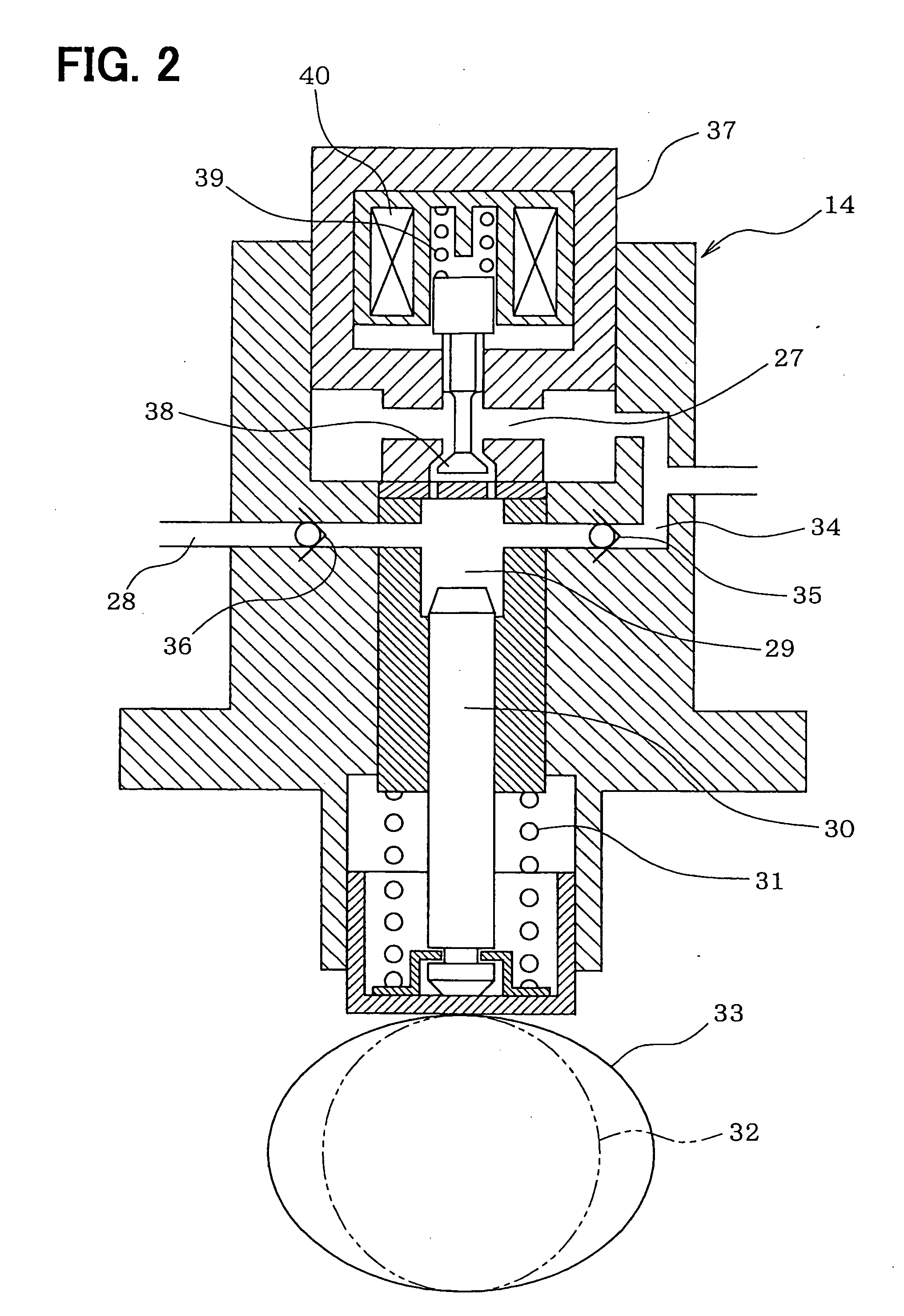
[0053] As explained above, the ECU 26 recognizes the phase of the pump cam 33 (the phase of the plunger 30) based on the crank angle sensed by the crank angle sensor 24 and controls the energization of the electromagnetic valve 37 based on the crank angle. Thus, the ECU 26 controls the opening timing and the closing timing of the electromagnetic valve 37 with respect to the reciprocating movement of the plunger 30. Therefore, the crank angle (the phase of the pump cam 33) cannot be sensed before the crank angle determination (the cylinder determination) based on the output signal of the crank angle sensor 24 and the like is completed during the engine starting period. At that time, the ECU 26 cannot control the opening timing and the closing timing of the electromagnetic valve 37 with respect to the reciprocating movement of the plunger 30.

[0054] Therefore, ...


PUM


Abstract

A high-pressure pump is formed with a secondary suction passage, which branches from a fuel suction passage and communicates with a pump chamber. Check valves for preventing a backflow of fuel are disposed respectively in the secondary suction passage and a discharge passage. An electromagnetic valve for regulating a fuel discharge quantity is disposed in the fuel suction passage. Normal control for controlling the fuel discharge quantity by controlling opening timing and closing timing of the electromagnetic valve with respect to reciprocating movement of a plunger is performed when an engine rotation speed is higher than a predetermined value during operation of an engine. Valve closing control for holding the electromagnetic valve at a closed state is performed when the engine rotation speed is equal to or lower than the predetermined value.

Description

CROSS REFERENCE TO RELATED APPLICATION [0001] This application is based on and incorporates herein by reference Japanese Patent Application No. 2004-93776 filed on Mar. 26, 2004. BACKGROUND OF THE INVENTION [0002] 1. Field of the Invention [0003] The present invention relates to a fuel supply system of an internal combustion engine improving a control method of a high-pressure pump. [0004] 2. Description of Related Art [0005] A direct injection type engine, which injects fuel directly into cylinders, needs to promote atomization of the injected fuel by increasing an injection pressure in order to ensure combustibility. Therefore, in the direct injection type engine, a low-pressure pump draws the fuel from a fuel tank, and a high-pressure pump pressurizes the fuel to a high pressure and pressure-feeds the fuel to fuel injection valves. For instance, a high-pressure pump disclosed in JP-A-2001-304071 (pages 3, 4, etc.) drives a plunger, which reciprocates in a pump chamber for suction...

Claims


Application Information

Patent Timeline
IPC IPC(8): F02M59/20F02D1/02F02D41/38F02M1/00F02M37/00F02M59/02F02M59/10F02M59/34F02M59/36F02M59/38F02M59/44F02M59/46F02M63/02
CPCF02D41/3845F02M37/0047F02M59/102F02M2200/09F02M59/447F02M63/0225F02M59/366
Inventor INAGUMA, YOSHITSUGUINOUE, HIROSHI
Owner DENSO CORP
Why Eureka
Try Eureka