
Method of microelectrode connection and connected structure of use threof

a micro-electrode connection and connection structure technology, applied in the direction of printed circuit assembling, printed circuit manufacturing, basic electric elements, etc., can solve the problems of short circuit patterns, incomplete connection of circuits between connection terminals, and the inability of the connection structure manufactured by the prior art method to operate normally, so as to enhance the reliability of electrical connections

Inactive Publication Date: 2005-09-29
LS MTRON LTD
View PDF9 Cites 37 Cited by
  • Summary
  • Abstract
  • Description
  • Claims
  • Application Information

AI Technical Summary

Benefits of technology

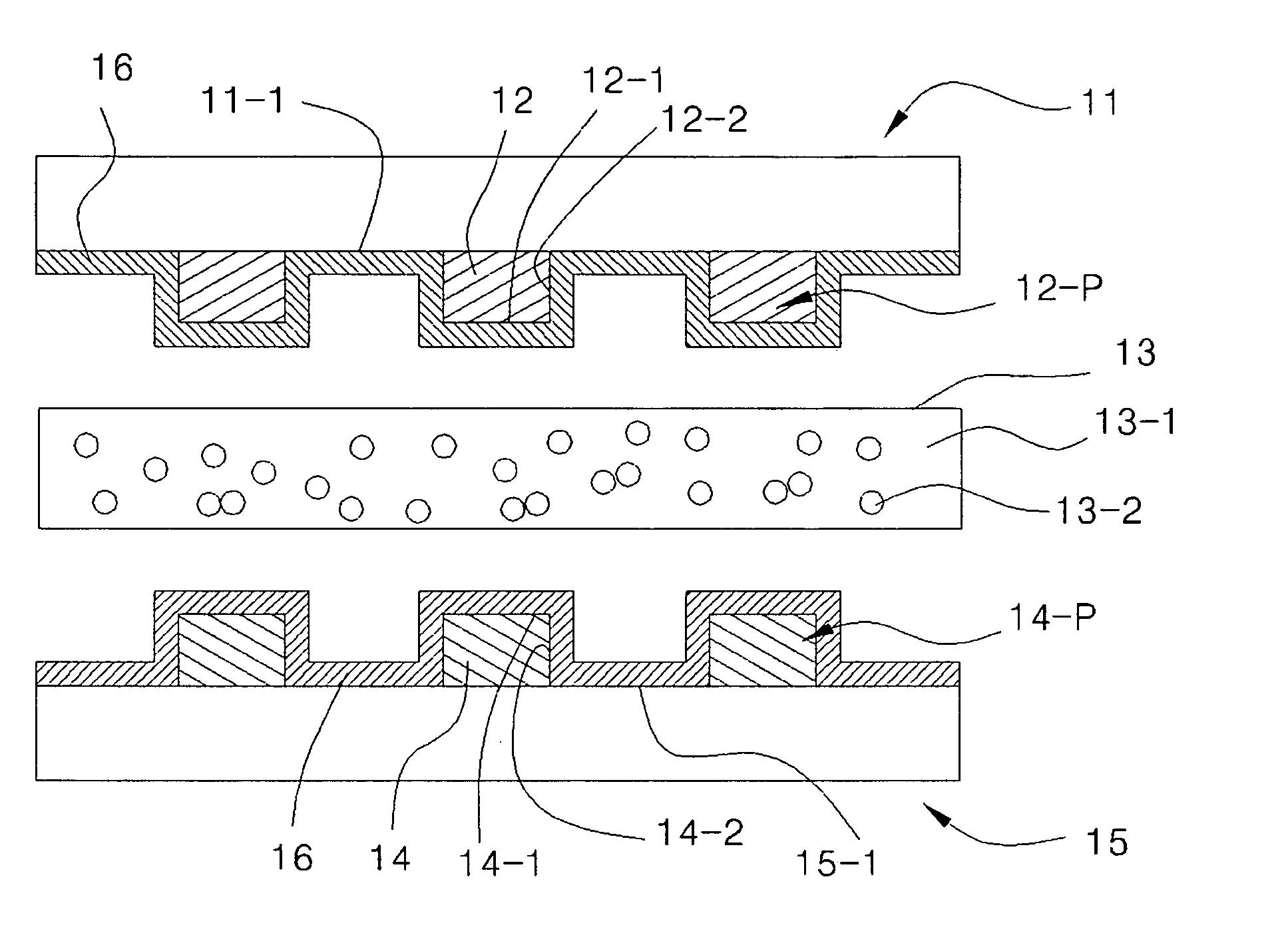
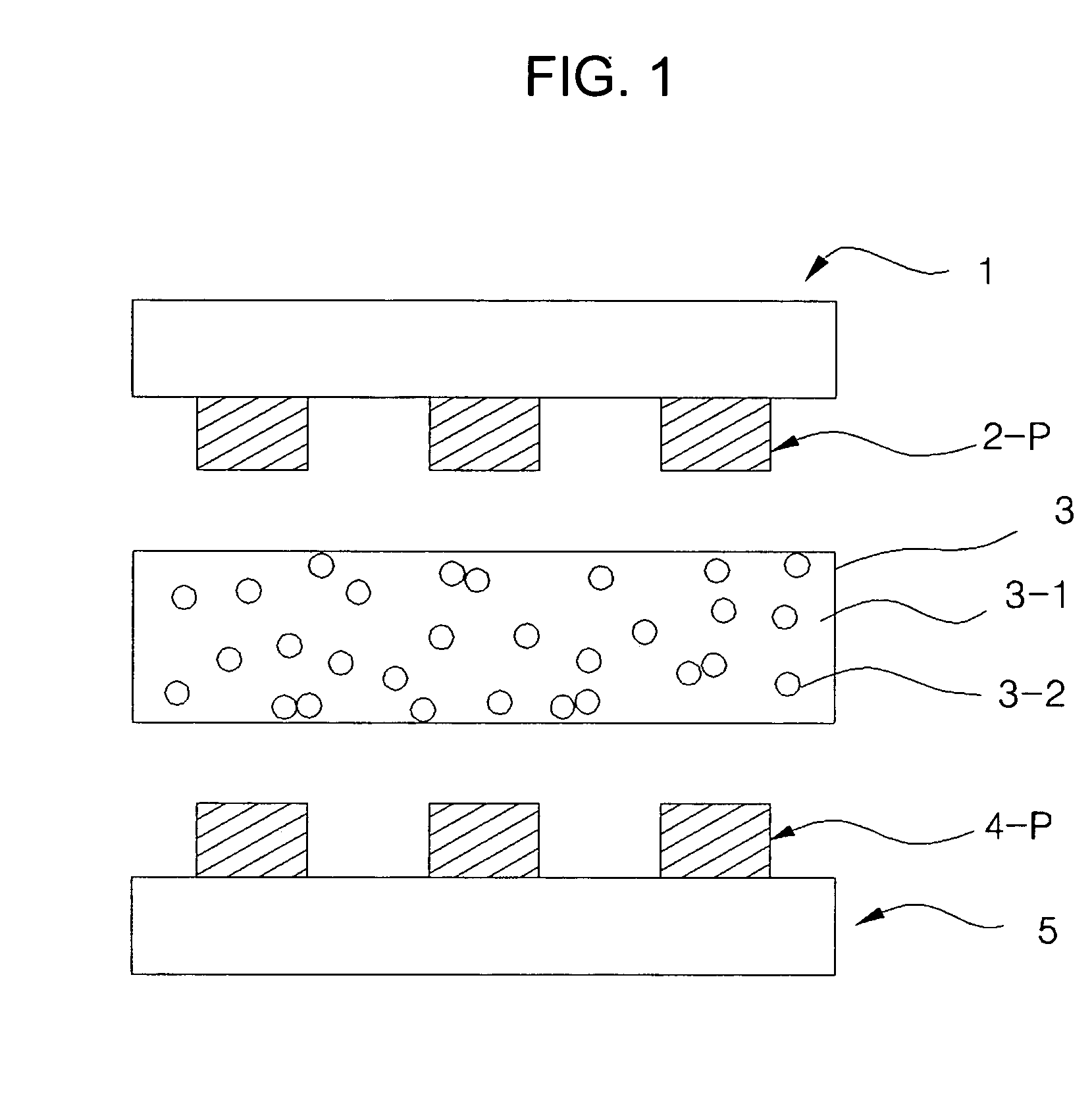
The patent text describes a method and structure for connecting microcircuits using an anisotropic conductive adhesive with conductive particles. The method involves preparing an insulating resin solution, applying it to each circuit board, aligning the circuit boards, interposing the adhesive, and applying heat and pressure to connect the circuits electrically and mechanically. The connection structure includes a first circuit board, second circuit board, conductive particles, insulating component, and insulating film layer. The technical effect of this invention is to enhance the reliability of electrical connection of microcircuit electrodes without shorting adjacent electrodes and provide a reliable connection structure.

Problems solved by technology

Therefore, the anisotropic conductive adhesive including the metal particles decreases relatively smaller a contact area between the circuits, thereby causing the circuits to connect incompletely between their connection terminals.
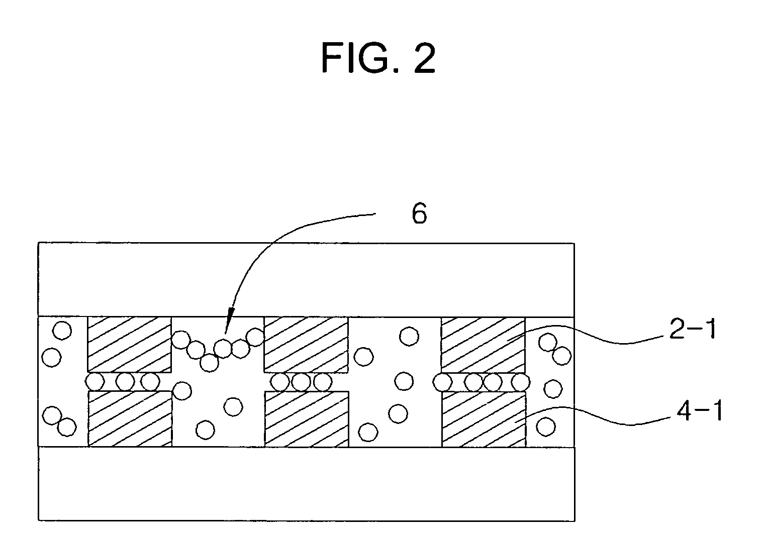
Further, the prior art microcircuit connection method has a problem that it often short the circuit patterns.
Therefore, a connection structure manufactured by the prior art method cannot be operated normally.
However, even if the metal particle coated with resin does not short the electrodes not to be connected, since the metal particle coated with resin as a core portion is not uniform and also it has relatively larger specific gravity than that of the insulating adhesive component, it is not uniformly dispersed in the insulating adhesive component.
Thus, an anisortopic conductive adhesive containing metal particle coated with resin does not properly connect the circuit boards with each other.
After the anisotropic conductive adhesive including the resin particle coated with metal component is disposed between the circuit boards, if both of the circuit boards are pressed by a predetermined pressure, a defect of electrical connection may be decreased because an area between the circuit boards is increased as the resin particle coated with metal component is transformed.
However, since the resin particle is coated with metal component, the anisotropic conductive adhesive including the resin particle coated with metal component also causes a short circuit of the electrodes that should not be connected, such that the circuit boards are not properly connected to each other.

Method used


Image

  • Method of microelectrode connection and connected structure of use threof
  • Method of microelectrode connection and connected structure of use threof
  • Method of microelectrode connection and connected structure of use threof

Examples


example 1

[0054] A polyester resin (Toyobo Co., Vylon 200™) was dissolved into a mixed solvent in which ketone and toluene are mixed in the weight ratio of 3:1, to prepare a solution containing 25% of solids. Subsequently, the resin solution was applied to electrode portion of TCP having a line width of 30 μm, a pitch of 60 μm, and a thickness of 18 μm, using a screen printer. And then, TCP coated with the resin solution was dried by hot wind at 70° C. for 5 minutes within an oven, thereby to obtain TCP coated with the insulating film. After that, the insulating film measures 1 μm thick using a micrometer.

example 2

[0055] The TCP coated with the insulating film was manufactured in the same method as Example 1 except that the vinyl acetate resin (Okong bond Co., PVAc 302™) was dissolved into a mixed solvent in which methl enthy ketone and toluene are mixed in the weight ratio of 3:1, to prepare a solution containing 25% of solids. Then, TCP coated with the insulation film having a thickness of 1 μm was manufactured using process of Example 1.

example 3

[0056] The TCP coated with the insulating film was manufactured in the same method as Example 1 except that the nitryl butadiene rubber (Nippon zeon Co., Nippol FN4002™) was dissolved into a mixed solvent in which methl enthy ketone and toluene are mixed in the weight ratio of 3:1, to prepare a solution containing 25% of solids. Then, TCP coated with the insulation film having a thickness of 1 μm was manufactured using process of Example 1.


PUM

PropertyMeasurementUnit
softening pointaaaaaaaaaa
thicknessaaaaaaaaaa

Abstract

Disclosed is a method for connecting microcircuits formed in a circuit board, such as a Tape Carrier Package (TCP), a Flexible Printed Circuit (FPC), a Liquid Crystal Display (LCD) or a printed circuit board using an anisotropic conductive adhesive including conductive particles, and the connection structure manufactured by the above method. The method comprises the steps of applying an insulating film layer to a circuit board having circuit patterns, and then boding them with an anisotropic conduction adhesive. The circuits that should not be connected by conductive particles included in the anisotropic conductive adhesive are prevented from a short-circuit

Description

TECHNICAL FIELD [0001] The present invention relates to a microcircuit connection method and a connection structure by the same, and more particularly to a method for connecting microcircuits formed in a circuit board, such as a Tape Carrier Package (TCP), a Flexible Printed Circuit (FPC), a Liquid Crystal Display (LCD) or a printed circuit board using an anisotropic conductive adhesive including conductive particles and the connection structure manufactured by the above method. BACKGROUND ART [0002] In the field of a semiconductor packaging or a liquid crystal display, an adhesive is used for fixing a chip to a board or connecting circuits to each other. In case of connecting a liquid crystal display panel with a Tape Carrier Package (TCP) or a Flexible Printed Circuit (FPC), or connecting a printed circuit board with a TCP or a FPC, an anisotropic conductive adhesive including conductive particles has been used. Recently, the anisotropic conductive adhesive is used for directly mo...

Claims


Application Information

Patent Timeline
Patent Type & Authority Applications(United States)
IPC IPC(8): H01L21/60H01L23/498H05K3/32H05K3/36
CPCH01L23/4985H01L24/29H01L2924/07802H01L2924/07811H01L2224/29444H01L2224/2929H01L2224/29455H01L2924/00013H01L2224/81903H01L2924/0665H01L2924/01045H01L2924/01006H01L2224/83851H01L2224/2919H01L2224/13016H05K2203/1189H01L24/83H01L2224/16H01L2224/2939H01L2224/2989H01L2224/73204H01L2224/83101H01L2224/8319H01L2224/838H01L2924/01005H01L2924/01015H01L2924/01027H01L2924/01033H01L2924/01058H01L2924/01061H01L2924/01078H01L2924/01079H01L2924/0781H05K3/323H05K3/361H05K2203/0759H01L2924/00014H01L2224/29099H01L2924/00H01L21/60
Inventor BYUN, JEONG ILLEE, KYUNG JOONLEE, MYUNG KYUPETER, CHUCKSIN
Owner LS MTRON LTD
Learn More