
Detector with tunable spectral response

Active Publication Date: 2005-09-29
STC UNM
View PDF2 Cites 27 Cited by
  • Summary
  • Abstract
  • Description
  • Claims
  • Application Information

AI Technical Summary

Benefits of technology

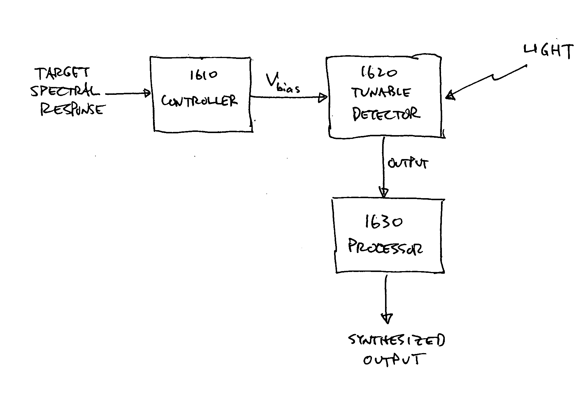
[0014] In another aspect of the invention, processing is used to further enhance and / or diversify the tunability of the tunable detector. In one approach, the detector is tuned to different spectral responses and the detector outputs for each of these are combined in a manner so that the combined output effectively synthesizes some desired spectral response. The desired spectral response may be a response that the detector itself is not physically capable of generating. For example, the synthesized spectral response may have a center wavelength not attainable by the detector or a spectral width that is narrower than that of the detector at any applied bias voltage.
[0016] In one application, this approach can be used to emulate a multispectral or hyperspectral sensor. Such a sensor has a number of bands and outputs a separate signal for each band. Weights are determined for emulation of each of the bands. The tunable detector cycles through its bias voltages to produce outputs that correspond to its basis spectral responses. These outputs are combined using the weights for band 1 in order to synthesize the output for band 1, combined using the weights for band 2 to synthesize the output for band 2, and so on. Thus, a single detector structure (or arrays of detectors for imaging applications) can be used to perform hyperspectral or multispectral imaging, thereby reducing the cost and complexity of many applications.

Problems solved by technology

However, a mechanical switching or tuning system limits the frame-rate of the device and can be cumbersome and prone to mechanical failure.
On the other hand, the use of multiple focal planes typically requires complex optical systems, which also lead to bulky and expensive solutions that are limited in the total number of available spectral bands.
However, these cameras are limited to a very small number of spectral bands, typically two or three, and require a complex detector structure and read-out electronics just to achieve that.
Furthermore, they are typically limited to switching between the two spectral bands, which are fixed in spectral response.
They typically cannot implement continuous or fine-tuning of the spectral response.

Method used


Image

  • Detector with tunable spectral response
  • Detector with tunable spectral response
  • Detector with tunable spectral response

Examples


Embodiment Construction

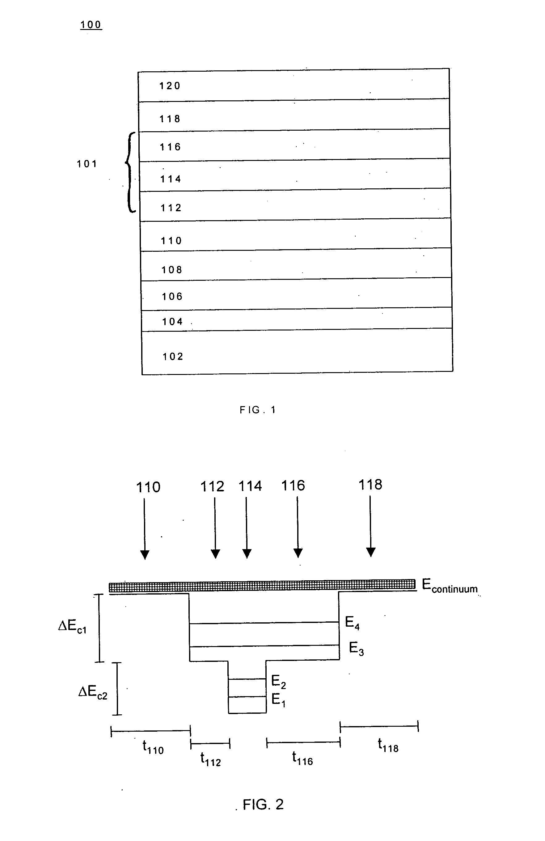
[0037] Turning now to FIG. 1, a cross-sectional view of an example DWELL structure 100 is illustrated. DWELL structure 100 includes multiple layers 104-120 fabricated on a substrate 102. The layers include a buffer region 104, an etch-stop region 106, a conductive region 108, a barrier region 110, an absorbing region 101, another barrier region 118 and another conducting region 120. In this example, the absorbing region 101 includes well regions 112 and 116 and quantum dot region 114 located between the two well regions 112 and 116.

[0038]FIG. 1 will be discussed in the context of a particular embodiment and is simplified for ease of discussion. Thus, it is not intended to be limiting. For example, other embodiments may use some, all or none of the specific regions shown in FIG. 1. The basic structure may be used with certain regions omitted and / or additional regions inserted. The regions are shown in FIG. 1 without lateral shape when, in fact, the lateral shapes of the regions may ...


PUM


Abstract

A semiconductor detector has a tunable spectral response. These detectors may be used with processing techniques that permit the creation of “synthetic” sensors that have spectral responses that are beyond the spectral responses attainable by the underlying detectors. For example, the processing techniques may permit continuous and independent tuning of both the center wavelength and the spectral resolution of the synthesized spectral response. Other processing techniques can also generate responses that are matched to specific target signatures.

Description

CROSS-REFERENCE TO RELATED APPLICATION [0001] This application claims priority under 35 U.S.C. § 119(e) to U.S. Provisional Patent Application Ser. No. 60 / 505,076, “Spectrally adaptive quantum dots in a well detector,” filed Sep. 23, 2003. The subject matter of the foregoing is incorporated herein by reference in its entirety.BACKGROUND OF THE INVENTION [0002] 1. Field of the Invention [0003] This invention relates generally to detectors with tunable spectral responses, including for example infrared (IR) detectors. [0004] 2. Description of the Related Art [0005] For many applications in infrared sensing, it would be desirable to use a focal plane array (hereinafter referred to as “FPA”) with a tunable spectral response that can be tuned to aid in the detection of a particular type of target or the classification of a target to one of known classes of targets. The spectral response ideally could be optimized for use under particular imaging or detection / classification scenarios or t...

Claims


Application Information

Patent Timeline
IPC IPC(8): G01J1/00G01J3/28G01J3/32G01J3/50H01J5/16H01J40/14H01LH01L27/146
CPCB82Y10/00G01J3/2803H01L27/14649G01J3/32G01J3/2823
Inventor KRISHNA, SANJAYTYO, J. SCOTTHAYAT, MAJEED M.RAGHAVAN, SUNILSAKOGLU, UNAL
Owner STC UNM
Learn More