System for electric generating using accumulation pressure

a technology of accumulation pressure and electric generating equipment, which is applied in the direction of electric generator control, machines/engines, mechanical equipment, etc., can solve the problems of inability to use as electric generating equipment and more consumption, and achieve the effect of reducing the volume and improving the rotating

Inactive Publication Date: 2005-09-29
YEH MING SHYUAN
View PDF10 Cites 15 Cited by
  • Summary
  • Abstract
  • Description
  • Claims
  • Application Information

AI Technical Summary

Benefits of technology

[0007] When in actual operation of the electric generating system of the present invention, the pressure-accumulating unit continuously releases a quantity of liquid fluid (such as the liquid water, oil etc.) in a high speed by means of compressed gas, the liquid fluid released in the high speed forms a spraying flow to rotate a turbine of the energy-converting unit, the turbine thereby creates a better rotating effect.
[0008] And before normal electric generating of the entire electric generating system, pre-stored electric power of an electric cell is used (or by way of direct pressurizing of a high-pressure gas bottle) to make the pressure-accumulating unit get a working pressure sufficient for driving the energy-converting unit to run; and after power generating of the electric generating system, a part of the electric power is switched to afford running a pressurizing pump of the pressure compensation unit, the fluid recovered by the pressurizing pump is pressurized and injected into a pressure-accumulating cylinder of the pressure-accumulating unit; and during supplying fluid in a recycling mode, the pressure-accumulating cylinder will compress the internal gas to reduce its volume by injection of the fluid, thus the pressure-accumulating cylinder can get an effect of pressure compensation; so that after normal electric generating of the electric generating system, supplying of electric power of the electric cell is stopped.
[0009] Especially, when in electric generating of the entire electric generating system, the pre-stored electric power is converted into compressive kinetic energy for rotating the turbine; or a kind of pre-stored compressive kinetic energy (from the high-pressure gas bottle) is formed for rotating the turbine, then the turbine actuates the electric generator to further convert the kinetic energy into electric power, and a part of the electric power is converted into compressive kinetic energy to maintain running of the entire electric generating system; after suitable amount of energy consumption, an object of sustaining electric generating by the mode of converting of energy can be realized. This not only can use the electric power generated as auxiliary electric power, but also no problem of public pollution will be induced during the process of operation of the electric generating system by the fact that there is no burning of any energy source.

Problems solved by technology

However, spare electric generators (or small electric generators) seen in multi-storied buildings mostly use combustible oil as the energy source for running of engines, and the engines actuate the electric generators; this not only consumes more cost for electric generating, but also can derive pollutions of air, noise etc., and long-time running in high temperatures of the engines may result mechanical wear, the engines can only be used as urgent spare power sources for temporary operation, and are unable used as electric generating equipment for long-time sustaining operation.

Method used


Image

  • System for electric generating using accumulation pressure
  • System for electric generating using accumulation pressure
  • System for electric generating using accumulation pressure

Examples


Embodiment Construction

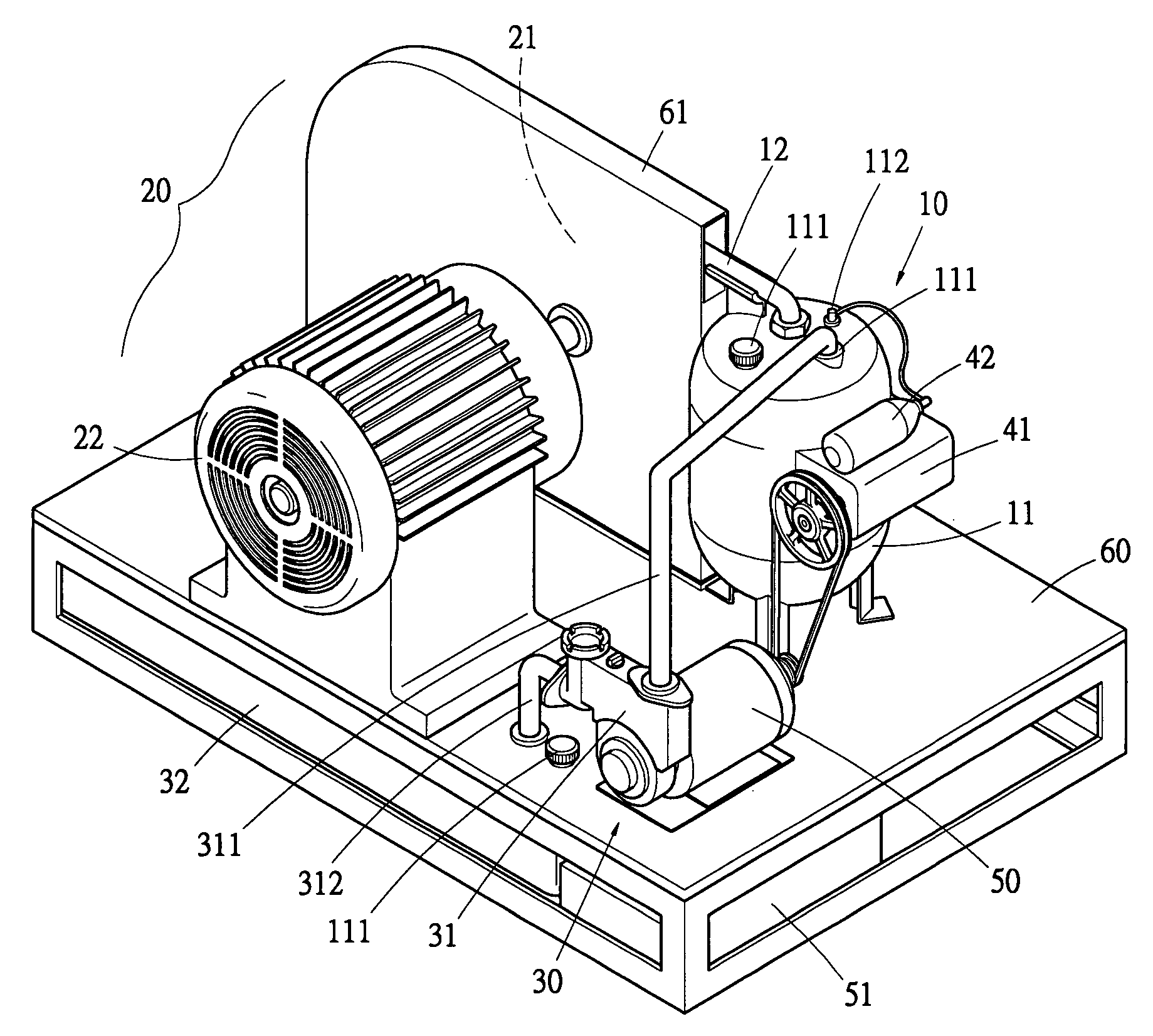
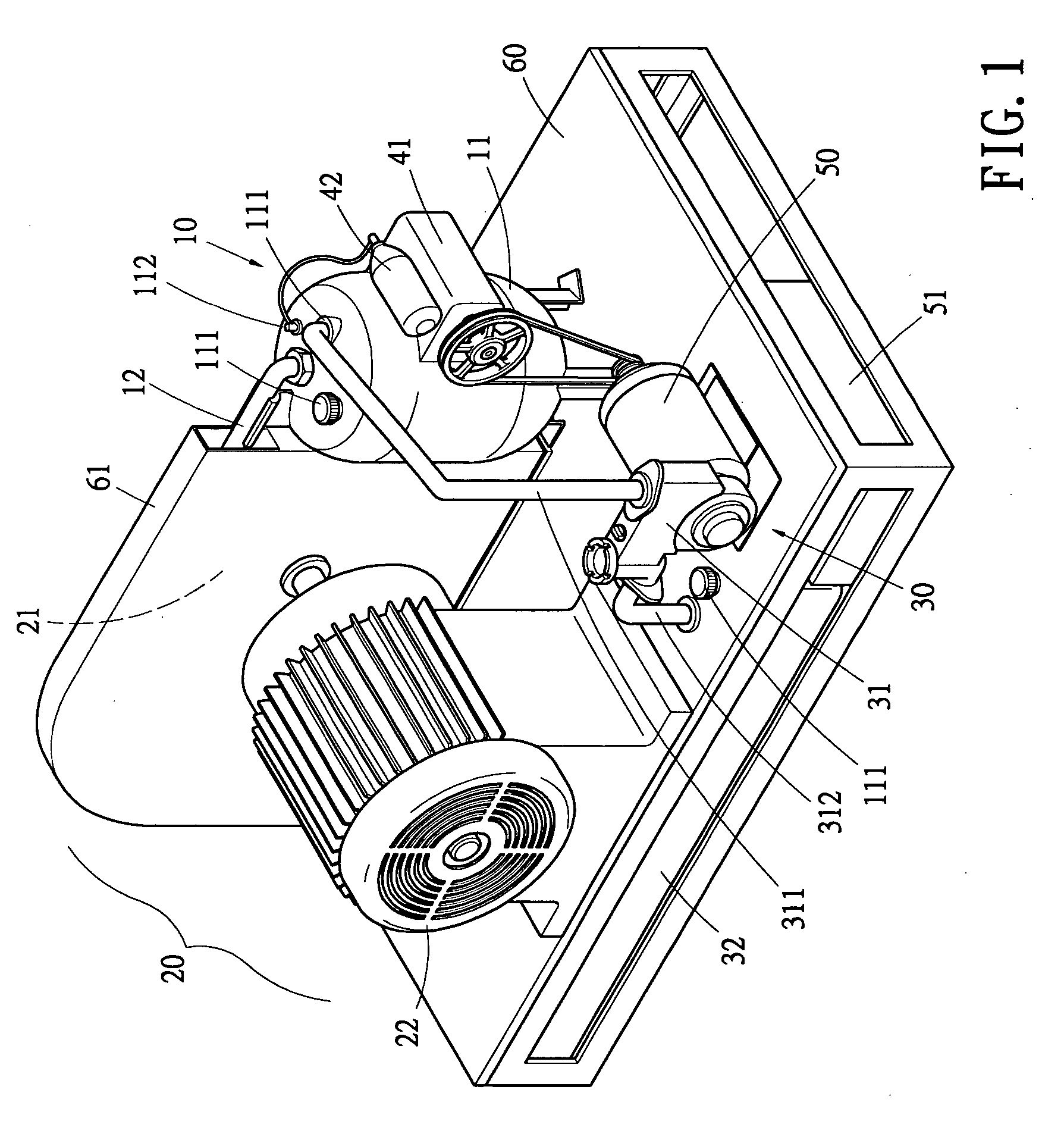
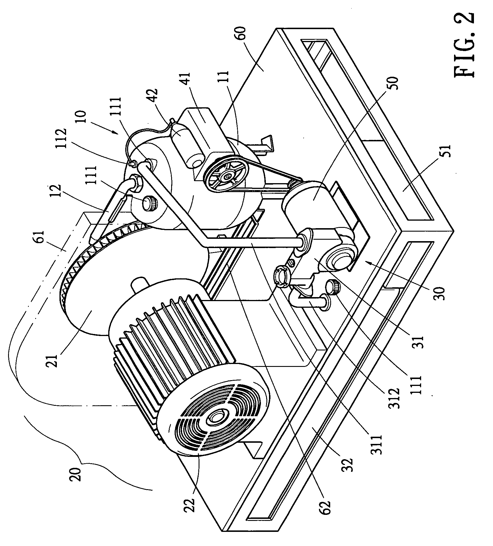
[0016] Referring to FIGS. 1 and 2 showing the structural combination of the system for electric generating using accumulation pressure of the present invention, the entire electric generating system basically is composed of a pressure-accumulating unit 10, an energy-converting unit 20 and a pressure compensation unit 30; and a base 60 is provided to function as a base body for mounting the abovementioned units and their related components. Wherein:

[0017] The pressure-accumulating unit 10 is used to store fluid with adequate pressure and amount; the fluid is released continuously with a high speed in operation. In the present embodiment, the pressure-accumulating unit 10 is provided with a pressure-accumulating cylinder 11 to store liquid fluid (such as liquid water, oil etc.) and to compress gas, the pressure-accumulating cylinder 11 is provided with fluid injection holes 111 for fluid complementing and inputting in a recycling mode, and with a gas injection hole 112 connecting wit...


PUM


Abstract

The electric generating system comprises: a pressure-accumulating unit, an energy-converting unit and a pressure compensation unit; wherein fluid stored in the pressure-accumulating unit is released continuously with a high speed to form a spraying flow to drive the energy-converting unit to thereby further convert kinetic energy into electric energy; and the pressure compensation unit pressurizes the fluid and injects it into the pressure-accumulating unit to continuously supply required fluid and maintain a stable working pressure, this can afford the electric power requirement for outputting of a posterior delivery and distributing equipment.

Description

BACKGROUND OF THE INVENTION [0001] 1. Field of the Invention [0002] The present invention is related to a technique to convert energy to achieve an object of sustaining electric generating, and especially to provide an auxiliary electric power supplying system without energy burning or public pollution. [0003] 2. Description of the Prior Art [0004] Looking around the tendency of requirement and supplying of energy of the world, the situation of energy sources and the environment of management of domestic as well as foreign energy sources have been changed; in order to follow the market development of the global energy sources as well as the impact of the problem of pollution induced by using energy sources; governments pay much efforts to promote development and application of separated and clean electric generating with an object of hoping to build electric generating systems at the users' terminals all over their countries, this is different from the large scaled and concentrated ...

Claims


Application Information

Patent Timeline
Patent Type & Authority Applications(United States)
IPC IPC(8): F03B17/00H02P9/04
CPCY02E10/20F03B17/005
Inventor YEH, MING-SHYUAN
Owner YEH MING SHYUAN
Why Eureka
Try Eureka