
Charging/discharging management system for lithium battery packs

a lithium battery and management system technology, applied in battery overcharge protection, safety/protection circuits, transportation and packaging, etc., can solve the problems of not being very effective in the real application, not being able to meet the requirements of charging/discharging systems, and relatively restricted use conditions of lithium batteries, so as to achieve more consistent and efficient battery performance and consumption less energy

Inactive Publication Date: 2005-09-29
LI WENMAN
View PDF5 Cites 16 Cited by
  • Summary
  • Abstract
  • Description
  • Claims
  • Application Information

AI Technical Summary

Benefits of technology

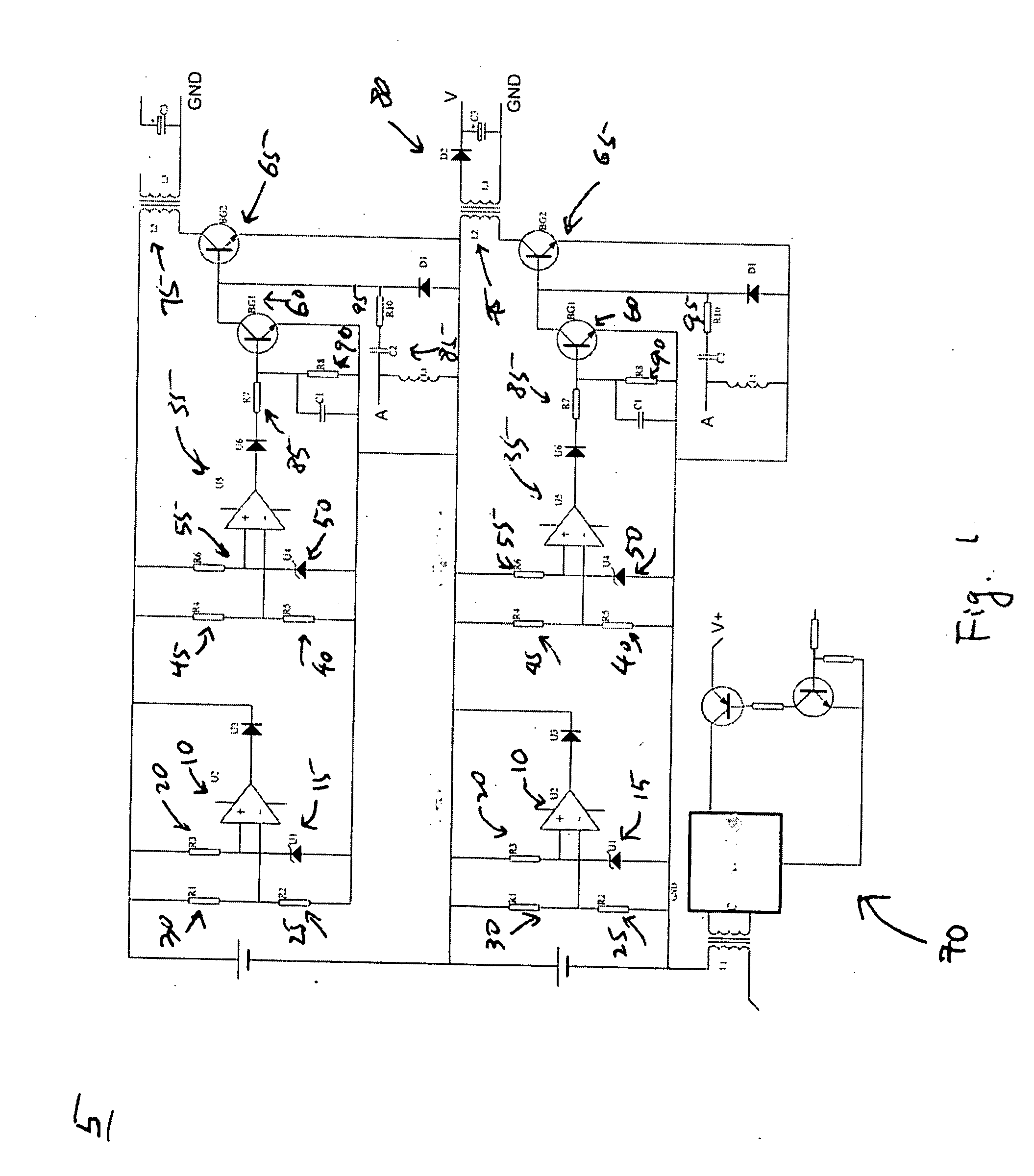
[0004] This invention overcomes the drawbacks of aforementioned two approaches and provides a new low-cost circuit design for the battery pack that consumes less energy and provides a more consistent and efficient battery performance. The new circuit design has the following features.
[0006] 2. Charging balance protection uses circuits consisting of an OP AMP (voltage comparator) and a DC inverter: when any battery unit in a battery pack reaches its upper voltage threshold, the DC inverter circuit goes into action; the charging energy for that battery unit is fed back to the entire battery pack. Thus, the charging energy can be effectively utilized to increase charging efficiency and decrease temperature raised on a charging system. This improves reliability of a charging system.

Problems solved by technology

However, the usage conditions for a lithium battery are relatively restricted.
However, it becomes quite challenge for a charging / discharging system of a lithium battery pack that has 10 or more serially connected battery units.
However, it's not very effective in the real applications.
This cutoff approach can't compensate this problem.
The second single unit charging approach is more effective but it costs too high.
Especially, the complicated structure and interface creates some difficulties in practical application.

Method used


Image

  • Charging/discharging management system for lithium battery packs

Examples


Embodiment Construction

[0010] For a lithium battery under a normal working condition, its upper voltage threshold is below 4.2V and its lower voltage threshold is above 2.75 V. Based on this characteristic, a pair of two OP AMPs or two comparators can accomplish the objectives of cutting off a charging power supply when the voltage of a battery reaches the upper threshold, and cutting off a load when it reaches the lower threshold. This circuit is called the threshold circuit. In FIG. 1, U210 is a lower voltage threshold comparator used for discharging; U210 compares a reference voltage (between R320 and U115) at the positive end of input and a battery input (between R130 and R225) at the negative end. When the voltage of a battery decreases, the electrical potential at the negative end also decreases accordingly. When the electrical potential reaches or falls below the reference voltage, the comparator U210 raises the output voltage to a high level; this will then trigger an electronic switch or a relay ...


PUM


Abstract

This invention is a management protection circuit to be used with a battery pack to prevent the charging or discharging of the battery from exceeding the upper and lower voltage thresholds. The over-discharging protection adopts a high accuracy, low power consumption, four OP AMPs comparison circuit. Its static working current is less than 0.3 mA. The charging balance protection adopts a combined circuit of a high accuracy, low power consumption, four OP AMPs comparison circuit and a direct current inverter. When any of battery units in a battery pack reaches the upper voltage threshold of charging condition, the inverter goes into an active state and takes the charging electrical energy back to the charging system. Thus, the electrical energy can be fully utilized. It also reduces the temperature raised on the charging system and increases the system's reliability.

Description

BACKGROUND OF THE INVENTION [0001] A lithium battery as a new type of rechargeable battery has wide applications due to its high quality and pollution-free feature. In many areas, a lithium battery has gradually replaced other types of rechargeable batteries. However, the usage conditions for a lithium battery are relatively restricted. Because an improper usage can reduce the battery's life span and damage the battery, adding a protection circuit for charging or discharging a battery to the commercial lithium batteries can prevent the improper usage from happening. For a single unit lithium battery, a charging / discharging protection circuit is installed to meet the normal usage conditions; the battery provides a steady output voltage of 3.6V; during charging, the upper voltage threshold should not exceed 4.2 V, while during discharging the lower voltage threshold should not go down below 2.75 V. And the voltage variances for upper and lower voltage thresholds should maintain within...

Claims


Application Information

Patent Timeline
IPC IPC(8): H02J7/00
CPCH02J7/0029H02J2007/004H02J2007/0037H02J7/00302H02J7/00306
Inventor LI, WENMAN
Owner LI WENMAN
Learn More