Magnetic sensor, production process of the magnetic sensor and magnetic array suitable for the production process

a technology of magnetic sensor and production process, which is applied in the direction of galvano-magnetic hall-effect devices, magnetic bodies, instruments, etc., can solve the problems of deteriorating the detection accuracy of the magnetic field and the hysteresis of the magnetic sensor, and achieve the effect of efficiently magnetizing the aforesaid bias magnet film and maintaining the detection accuracy

Inactive Publication Date: 2005-09-29
YAMAHA CORP
View PDF2 Cites 7 Cited by
  • Summary
  • Abstract
  • Description
  • Claims
  • Application Information

AI Technical Summary

Benefits of technology

[0011] Accordingly, one of objects of the present invention is to provide a magnetic sensor capable of satisfactorily maintaining a detection accuracy even after a great external magnetic field is applied thereto. Further, another object of the present invention is to provide a magnetic sensor capable of efficiently magnetizing the aforesaid bias magnet films, a production process of the magnetic sensor and a magnet array suitable for the production process.

Problems solved by technology

As a result, the magnetic sensor has a hysteresis again with respect to the external magnetic field, entailing a problem of deteriorating the detection accuracy of the magnetic field.

Method used


Image

  • Magnetic sensor, production process of the magnetic sensor and magnetic array suitable for the production process
  • Magnetic sensor, production process of the magnetic sensor and magnetic array suitable for the production process
  • Magnetic sensor, production process of the magnetic sensor and magnetic array suitable for the production process

Examples


Embodiment Construction

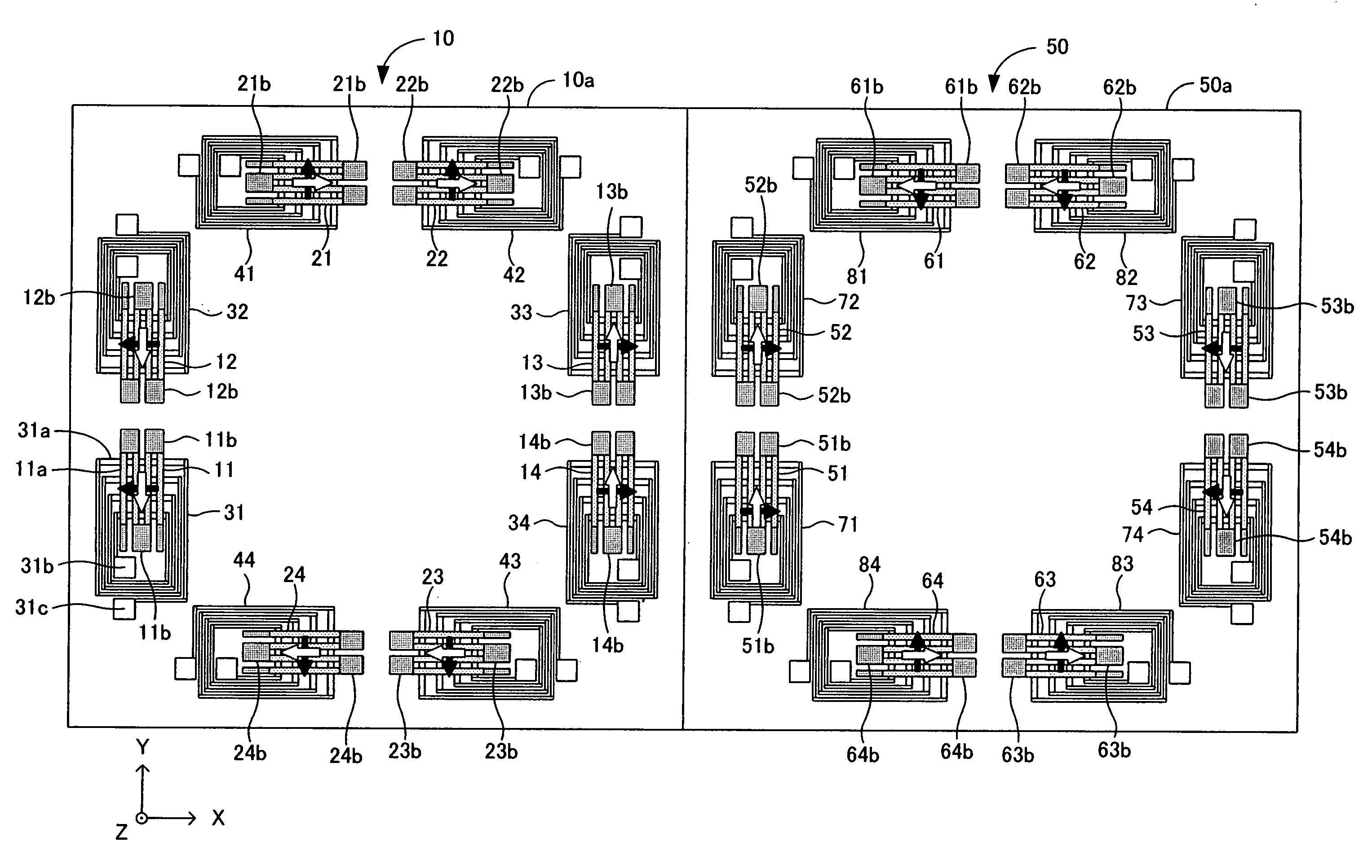
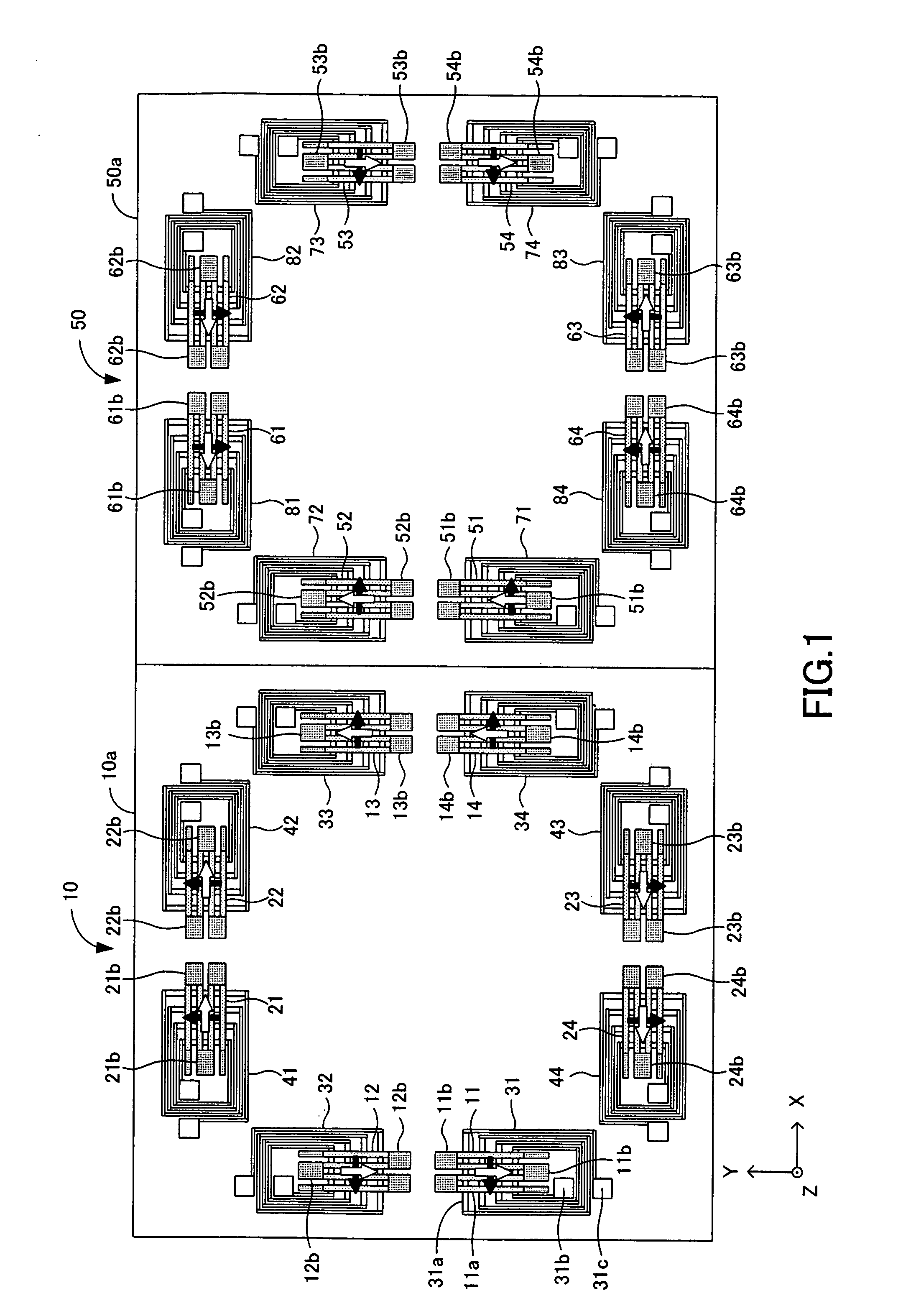
[0080] Embodiments of a magnetic sensor in accordance with the present invention will now be described with reference to the drawings. This magnetic sensor is classified into N-type and S-type depending upon a production process described later. FIG. 1 is a plan view wherein an N-type magnetic sensor 10 and an S-type magnetic sensor 50 are placed side by side. The N-type magnetic sensor 10 and the S-type magnetic sensor 50 have substantially the same shape and same configuration except that a direction of fixed magnetization in a pinned layer shown by black-solid arrows in FIG. 1 and a direction of magnetization in an initial state in a free layer shown by outline arrows in FIG. 1 are different from each other. Accordingly, the following explanation is mainly focused on the N-type magnetic sensor 10.

[0081] The magnetic sensor 10 comprises, as shown in FIG. 1, a single chip (a single substrate or a monolithic chip) 10a made of a quartz glass, which has a rectangular shape (almost sq...


PUM

PropertyMeasurementUnit
thicknessaaaaaaaaaa
thicknessaaaaaaaaaa
thicknessaaaaaaaaaa

Abstract

The present invention aims to provide a magnetic sensor provided with a magnetoresistive effect element capable of stably maintaining a direction of magnetization in a magnetic domain of a free layer. The magnetic sensor includes a magnetoresistive effect element provided with narrow zonal portions 11a . . . 11a including a pinned layer and a free layer. Disposed below both ends of the free layer are bias magnet films 11b . . . 11b composed of a permanent magnet that applies to the free layer a bias magnetic field in a predetermined direction and an initializing coil 31 that is disposed in the vicinity of the free layer and applies to the free layer a magnetic field having the direction same as that of the bias magnetic field by being energized under a predetermined condition. Further, magnetizing the bias magnet films and fixing the direction of magnetization of the pinned layer are performed by a magnetic field formed by a magnet array configured such that plural permanent magnets are arranged on a lattice point of a tetragonal lattice and a polarity of a magnet pole of each permanent magnet is different from a polarity of the other adjacent magnet pole spaced by the shortest route.

Description

BACKGROUND OF THE INVENTION [0001] 1. Field of the Invention [0002] The present invention relates to a magnetic sensor using a magnetoresistive effect element including a pinned layer and a free layer, a production process of the magnetic sensor and a magnet array suitable for the production process. [0003] 2. Description of the Related Arts [0004] Conventionally, a magnetoresistive effect element is applied to a magnetic sensor. For instance, the magnetoresistive effect element includes a giant magnetoresistive effect element (GMR element) or the like that is provided with a pinned layer having magnetization pinned (fixed) in a predetermined direction and a free layer in which the direction of magnetization is changed according to an external magnetic field and that presents a resistance value according to a relative relationship between the direction of magnetization in the pinned layer and the direction of magnetization in the free layer. In the magnetic sensor of this type, it i...

Claims


Application Information

Patent Timeline
Patent Type & Authority Applications(United States)
IPC IPC(8): G01D5/14H01L43/06G01D5/16G01R33/09H01F10/32H01F13/00H01F17/00H01F41/30H01L43/08
CPCB82Y25/00B82Y40/00G01D5/145G01R33/093H01F10/324H01F10/3295H01F17/0006H01F41/302Y10T29/49034Y10T29/49002H01F13/00H10N52/00
Inventor OOHASHI, TOSHIYUKIWAKUI, YUKIO
Owner YAMAHA CORP
Why Eureka
Try Eureka