
Quality printing method, printing machine, and corresponding printing substance

a printing method and printing machine technology, applied in the field of quality printing method, printing machine and corresponding printing substance, can solve the problems of easy blockage of required jets, large consumption of energy, and easy blockage of piezoelectric ink printing process

Inactive Publication Date: 2005-09-29
LPKF LASER & ELECTRONICS
View PDF4 Cites 40 Cited by
  • Summary
  • Abstract
  • Description
  • Claims
  • Application Information

AI Technical Summary

Benefits of technology

[0008] The object of the present invention is therefore to provide a printing process which has an improved printing quality and which requires much less energy for printing a printing point, but which at the same time allows a high printing speed with high resolution capacity. The object of the present invention is also to provide a corresponding printing machine and a corresponding printing substance with which the printing process according to the invention can be realized.

Problems solved by technology

However, these thermal ink printing processes have in turn the disadvantage that on the one hand they consume a great deal of energy for the printing of an individual printing point and on the other hand they are suitable only for printing processes which are water-based.
On the other hand, piezoelectric ink printing processes suffer from the disadvantage that the required jets are easily blocked, with the result that only special and expensive inks can be used for this.
However, in this process it is disadvantageous that the filling of the cells is very difficult due to the small diameter of the cells.
This severely restricts the variety of printing inks that can be used.
Moreover, a delay in boiling often occurs with the result that the temperature at which gas bubbles form in the printing substance cannot be predicted.
This means that the absorption—and the local heating of the printing substance associated therewith—takes place largely uncontrolled, which results i.a. in a marked variation in printing-point size.
In addition, the heat conduction in the absorption layer must not be ignored, with the result that a larger area of the absorption layer is necessarily heated, which likewise increases the required energy.

Method used


Image

  • Quality printing method, printing machine, and corresponding printing substance
  • Quality printing method, printing machine, and corresponding printing substance
  • Quality printing method, printing machine, and corresponding printing substance

Examples


Embodiment Construction

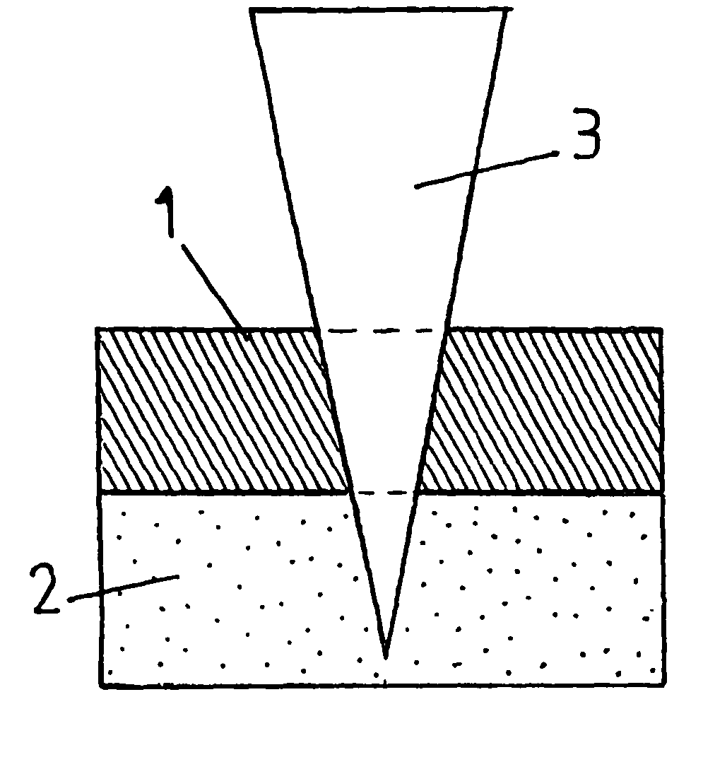
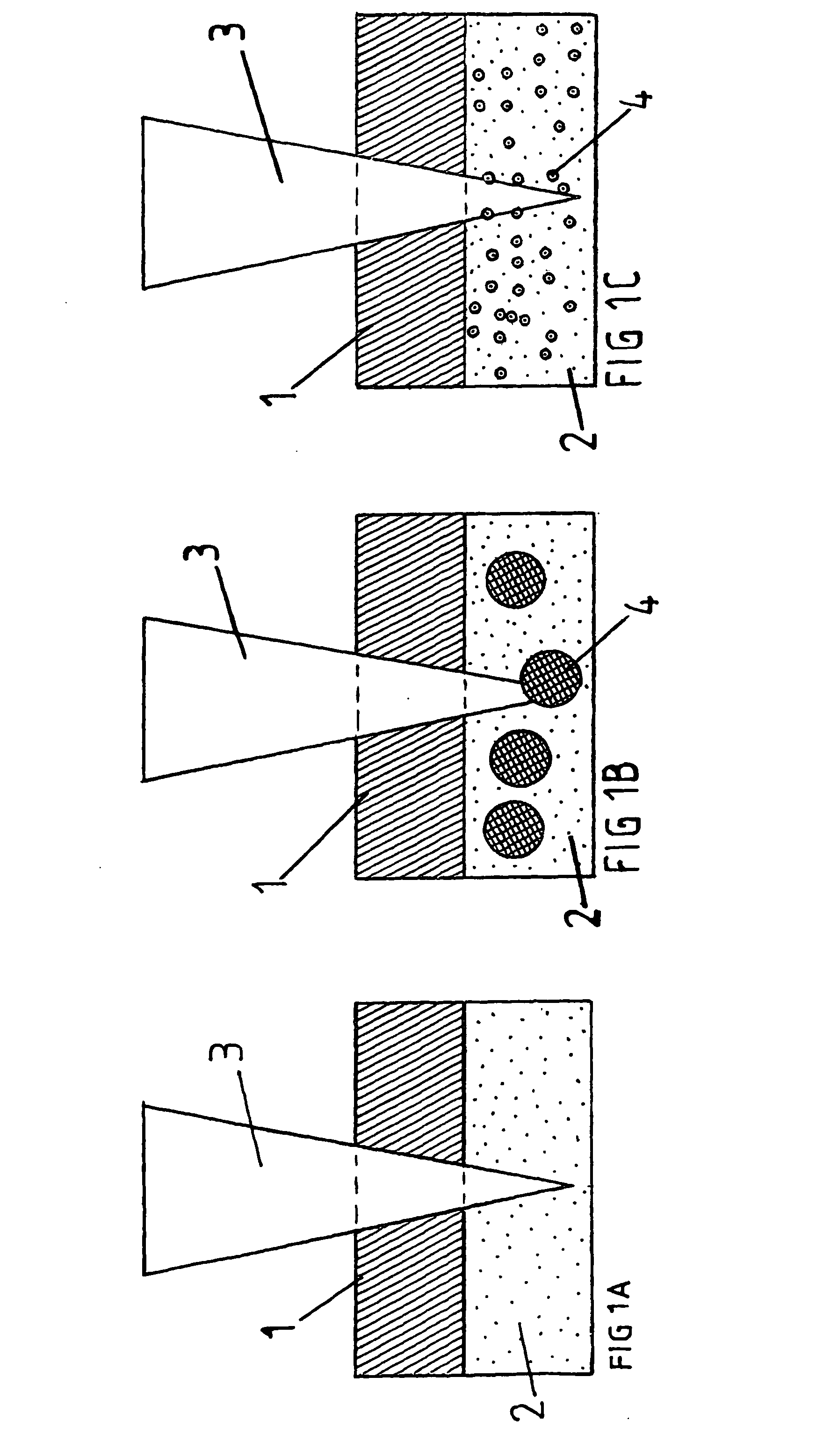
[0021] As regards the process, the object is achieved in that the energy is transferred from the electromagnetic radiation into the printing substance with the help of absorption bodies.

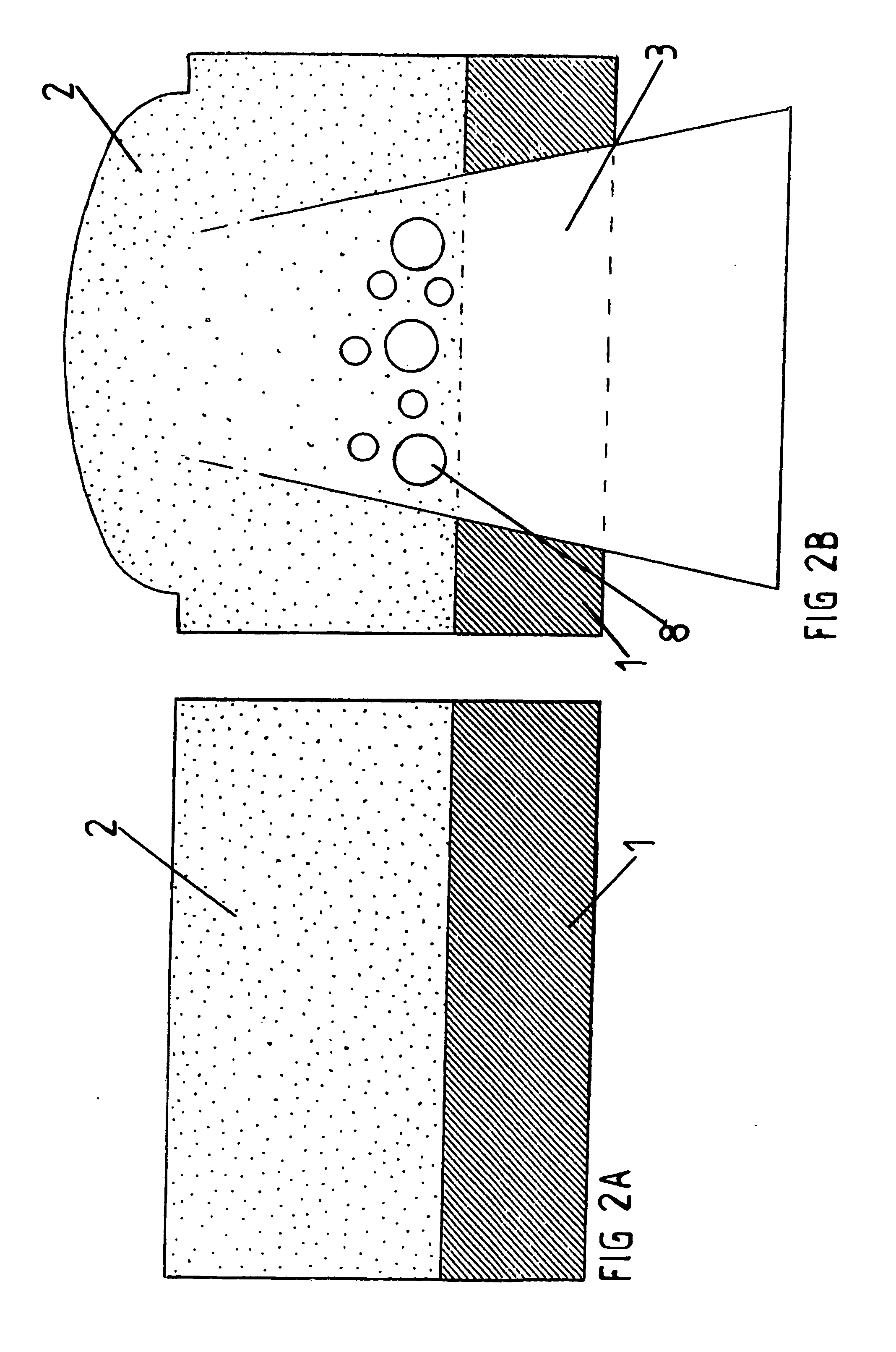
[0022] Without absorption bodies, the electromagnetic wave penetrates far into the printing substance and is absorbed along a relatively large area. To now achieve the necessary change in volume and / or position of the printing substance, a relatively large area of the printing substance must be heated until a gas bubble forms. The effect of using absorption bodies is that the electromagnetic wave is absorbed essentially at the surface of the absorption body, i.e. over a much smaller area. As a result, even with a very much smaller energy contribution, a heating occurs at certain points with the result that the desired change in volume and / or position of the printing substance already takes place earlier. Moreover, a delay in boiling can be effectively prevented through the presence alone of the boun...


PUM

PropertyMeasurementUnit
Timeaaaaaaaaaa
Timeaaaaaaaaaa
Timeaaaaaaaaaa

Abstract

A printing process for the transfer of printing substance (2) from an ink carrier (1) to an imprinting material (6), in which, with the help of an energy-emitting apparatus, which, during a process period, emits energy in the form of electromagnetic waves (3), and the printing substance (2) undergoes a change in volume and / or position, wherein, with the help of absorption bodies (4), energy is transferred from the electromagnetic waves (3) into the printing substance (2). The invention also includes an apparatus for practicing the process of the invention and a printing substance containing absorption bodies.

Description

BACKGROUND OF THE INVENTION [0001] The present invention relates to a printing process for the transfer of printing substance from an ink carrier onto an imprinting material, in which, with the help of an energy-emitting apparatus which emits energy during a process period in the form of electromagnetic waves, the printing substance undergoes a change in volume and / or position, and for example as a result a transfer of a printing point onto the imprinting material takes place, as well as a printing machine and a printing substance for this. [0002] By a printing process is meant primarily a process for the reproduction as often as required of text and / or image patterns by means of a printing plate which is re-inked after each impression. In general, a distinction is made here between four basically different printing processes. Thus firstly the relief printing process is known, in which the printing elements of the printing plate are raised, while the non-printing parts are recessed....

Claims


Application Information

Patent Timeline
IPC IPC(8): B41J2/05B41C1/10B41J2/44B41M5/24B41M5/382B41M5/385B41M5/392B41M5/46C09D11/02
CPCB41J2/0057B41M1/00C09D11/03B41J2/442B41M5/025B41M5/0052B41M5/38257B41M5/46B41M2205/02B41M2205/30
Inventor LEHMANN, UDOMEYER, DIRK
Owner LPKF LASER & ELECTRONICS
Learn More