Multi beam exposing device and exposing method using the same

a multi-beam exposing and exposing method technology, applied in the field of multi-beam exposing devices, can solve the problems of deformation and deviation of the position of the image projected on the exposure surface, deformation of the exposing head, and inability to strictly match the design circuit pattern, etc., to achieve high quality and high accuracy of plotting

Active Publication Date: 2005-09-29
ADTEC ENG +1
View PDF6 Cites 25 Cited by
  • Summary
  • Abstract
  • Description
  • Claims
  • Application Information

AI Technical Summary

Benefits of technology

[0039] Summing up the above descriptions, the exposing device according to the invention can appropriately detect the distortion of the plotted image which is varied with the lapse of time due to factors such as temperature or vibration when the exposure is performed with the beam

Problems solved by technology

This is a result of the lens for use in an illumination optical system or a focusing optical system in the exposing head having an inherent distortion characteristic.
In other wor

Method used


Image

  • Multi beam exposing device and exposing method using the same
  • Multi beam exposing device and exposing method using the same
  • Multi beam exposing device and exposing method using the same

Examples


Embodiment Construction

[0057] A description will be given below of a multi beam exposing device in a preferred embodiment according to the invention with reference to FIGS. 1 to 12.

[Configuration of Image Forming Apparatus]

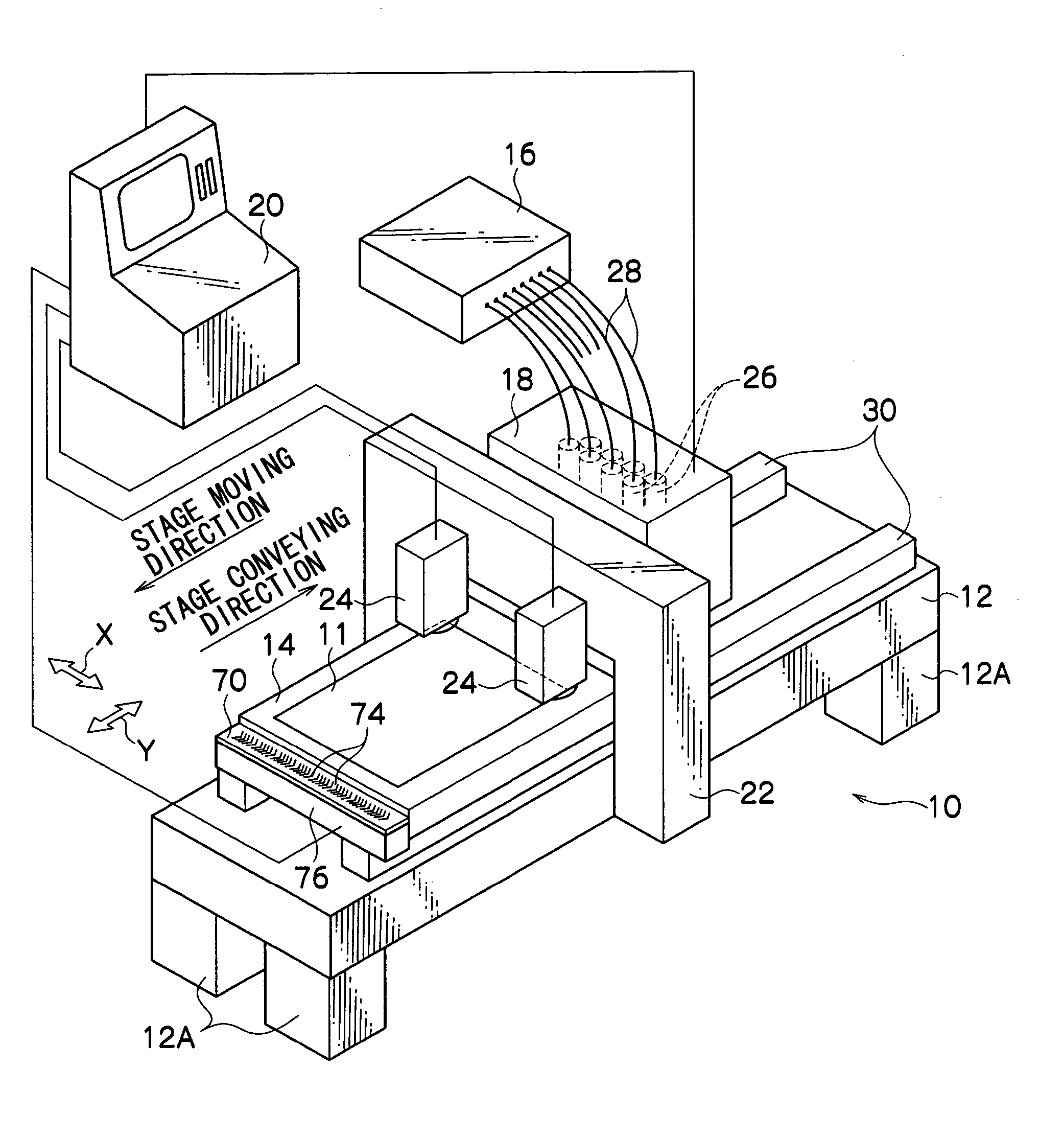
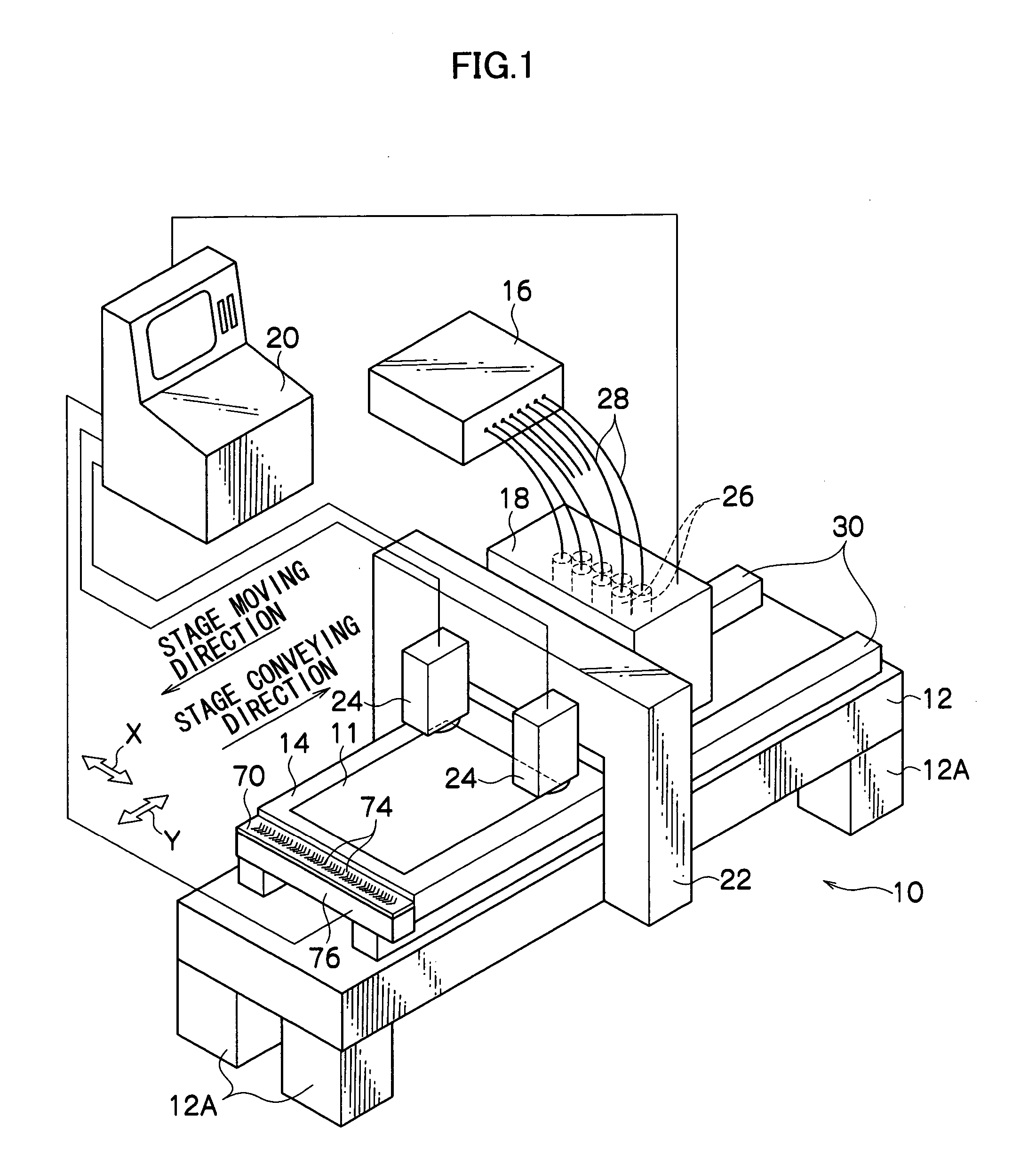
[0058] As shown in FIG. 1, an image forming apparatus 10 configured as a multi beam exposing device in a preferred embodiment according to the invention is of a so-called flat bed type, comprising: a table 12 supported by four leg members 12A; a moving stage 14 which moves on the table 12 in a direction indicated by an arrow Y in FIG. 1 and has a photosensitive material fixedly mounted thereon, the photosensitive material being that formed on a glass substrate, e.g., a printed circuit board (abbreviated as “a PCB”), a color liquid crystal display (abbreviated as “an LCD”) or a plasma display panel (abbreviated as “a PDP”); a light source unit 16 which emits a multi beam including an ultraviolet wavelength region and extending in one direction as a laser beam; an exposing head unit 18 ...


PUM


Abstract

An exposing device including means which has a plurality of pixels and modulates, per pixel, an optical beam irradiated from a light source, for exposing a plotted image on an exposure surface by modulating, per pixel, the plurality of pixels of the modulating means based on image data, the multi beam exposing device comprising: beam position detecting means for detecting exposure point positional information pertaining to an optical beam irradiated on the exposure surface from predetermined pixels to be measured of the modulating means; and positional deviation calculating means for calculating a relative positional deviation between positional information pertaining to the pixels to be measured of the modulating means and exposure point positional information pertaining to each of the optical beams projected at the exposure surface from each of the pixels to be measured detected by the use of the beam position detecting means, based on the two positional informations.

Description

CROSS-REFERENCE TO RELATED APPLICATION [0001] This application claims priority under 35 USC 119 from Japanese Patent Application No. 2004-96752, the disclosure of which is incorporated by reference herein. Reference is made to related Japanese Patent Application No. 2005-54942, the disclosure of which is incorporated by reference herein. BACKGROUND OF THE INVENTION [0002] 1. Field of the Invention [0003] The present invention relates to a multi beam exposing device for focusing and irradiating, per pixel, each of beams emitted from a means for selectively turning on or off a plurality of pixels such as a spatial light modulator disposed in an exposing head based on image data (i.e., pattern data), with an optical element such as a lens array, so as to expose a predetermined pattern. The present invention also relates to an exposure method using the multi beam exposing device. [0004] 2. Description of the Related Art [0005] In recent years, there has been developed a multi beam expos...

Claims


Application Information

Patent Timeline
IPC IPC(8): G02B26/00G03B21/13G03B27/72G03F7/20
CPCG03B21/13G03B27/72G03F7/70358G03F7/70275G03F7/70291G03F7/2057E02D29/1427E02D2600/20
Inventor FUKUDA, TAKESHI
Owner ADTEC ENG
Why Eureka
Try Eureka