Leader tape and magnetic tape cartridge using the same

a technology of magnetic tape and cartridge, which is applied in the direction of data recording, instruments, packaging, etc., can solve the problems of recording failure and information loss, inability to meet the requirements of the recording, and easy damage of the core, so as to prevent the increase of error rates

Inactive Publication Date: 2005-09-29
FUJIFILM CORP +1
View PDF2 Cites 15 Cited by
  • Summary
  • Abstract
  • Description
  • Claims
  • Application Information

AI Technical Summary

Benefits of technology

[0015] An object of the invention is to provide a leader tape not so much troubled by the increase in dropouts to be caused by transference of a drive reel or a leader block onto it during long-term storage or high-temperature running, and to provide a magnetic tape cartridge using the leader tape.
[0021] The leader tape of the invention is designed to have a specifically-defined surface roughness, and therefore, when it is wound up, a suitable distance may be formed between the faces of the wound tape. Therefore, since the pressure to it may be relieved, a leader block and others are prevented from being transferred to magnetic tapes. Also, the leader tape of the invention is designed to have a specifically-defined rate of stiffness of the leader tape and the magnetic tape in a machine direction (MD). Thus, in addition to the above effect, the leader tape may prevent the increase in error rates.

Problems solved by technology

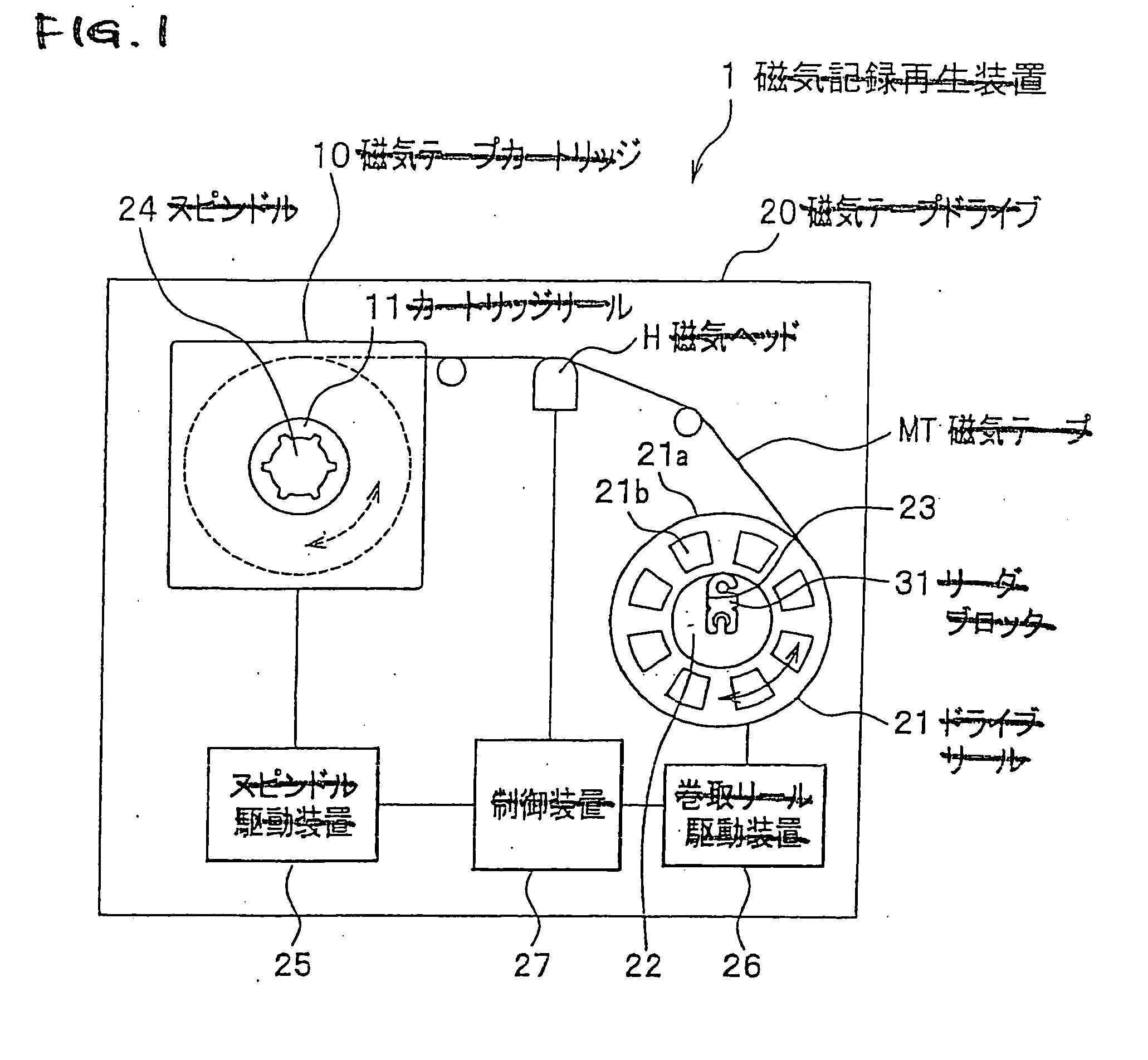
In the loading / unloading process as above where the magnetic tape is drawn out toward the side of the magnetic recording and reproduction device and its top end is wound up around the drive reel in the device, the top end of the magnetic tape is contacted with the tape guide and the magnetic head disposed along the tape-running route, while not accurately positioned relative to them, and in that condition, it is pulled and is therefore readily damaged.
Further, when some disorderly winding (e.g., protrusion) of the data recording magnetic tape occurs, the troubled site undergoes permanent deformation that causes dropout.
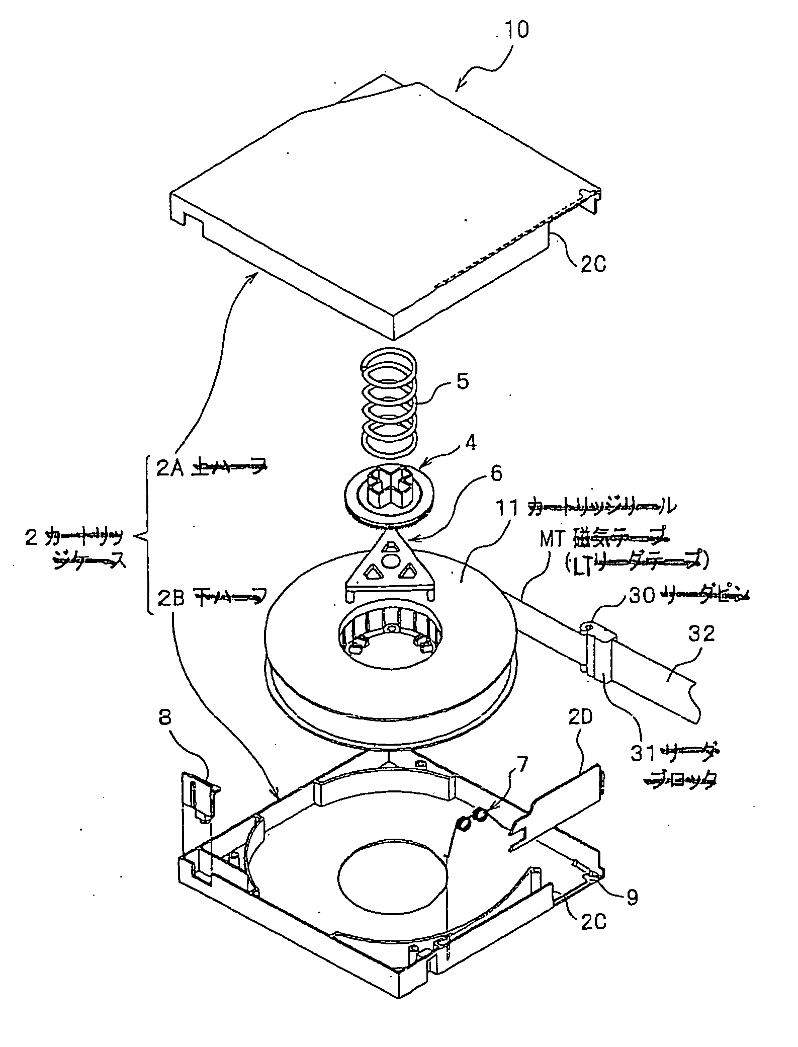
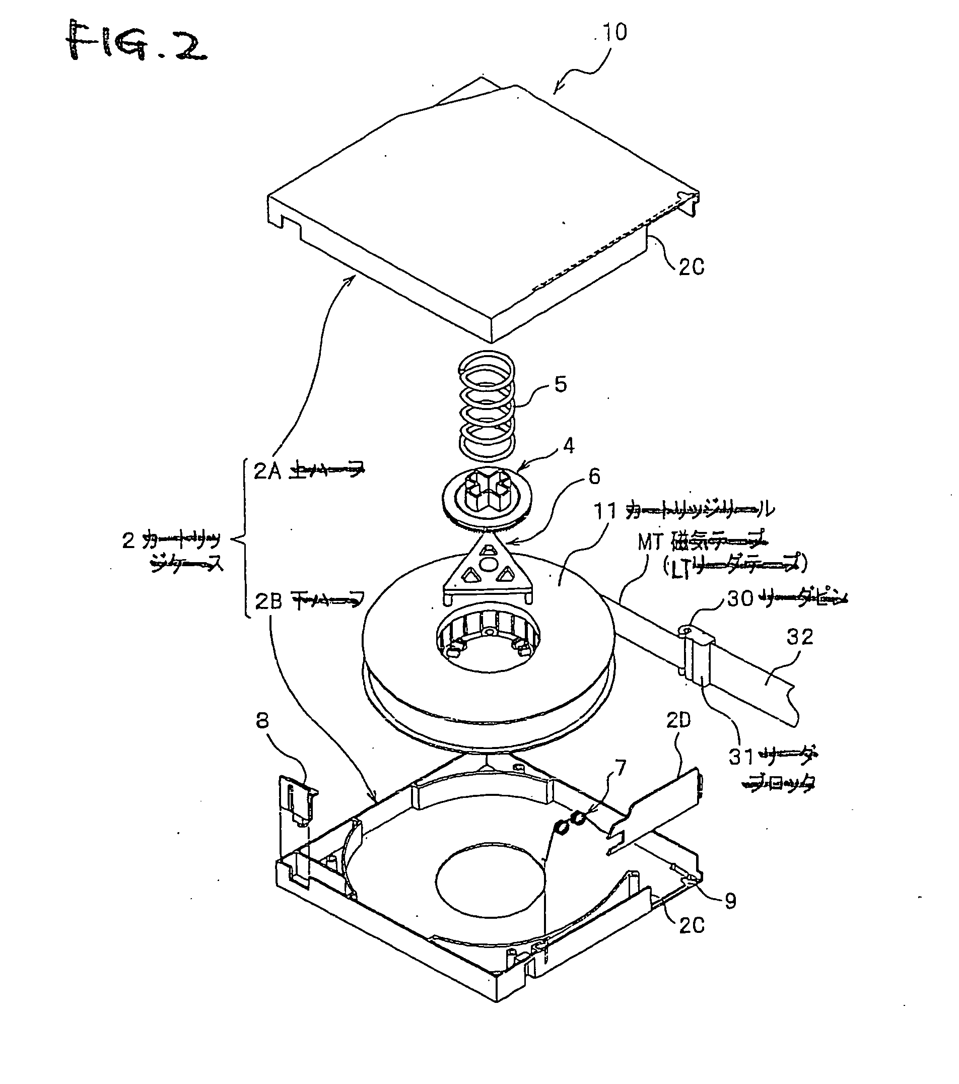
However, in such a conventional tape drive, the end face 40a may protrude above the core 41, as in FIG. 4B, depending on the dimensional accuracy of the leader block 40 that constitutes a part of the take-up face, and it may form an unacceptable level difference in the take-up face of the core 41.
The tape deformation transfer may cause a problem in that a suitable distance between the tape and the recording / reproducing head could not be ensured in the process of information recording / reproduction, and it may therefore cause recording failure and information loss.

Method used


Image

  • Leader tape and magnetic tape cartridge using the same
  • Leader tape and magnetic tape cartridge using the same
  • Leader tape and magnetic tape cartridge using the same

Examples


example 1

[0095] In the Examples, “part” is by weight.

Formation of Leader Tape:

[0096] Coating Composition for upper layer:

Ferromagnetic metal powder100 parts coercive force Hc: 191 kA / m (2400 Oe)specific surface area by BET method: 62 m2 / gcrystallite size: 110 angstromssaturation magnetization σs: 117 A · m2 / kgmean major axis length: 45 nmmean acicular ratio: 5pH: 9.3Co / Fe: 25 atm. %Al / Fe: 7 atm. %Y / Fe: 12 atm. %Phenylphosphonic acid:2 partsVinyl chloride-based copolymer (Nippon Zeon's MR-110)5 parts

[0097] (—SO3Na content: 5×10⁻⁶ eq / g, degree of polymerization: 350), epoxy content: 3.5 weight % as monomer unit)

Polyester-polyurethane resin12parts(neopentylglycol / caprolactone polyol / MDI = 0.9 / 2.6 / 1by weight, —SO3Na content: 1 × 10⁻⁴ eq / g)α-alumina (mean particle size: 0.3 μm)10partsCarbon black (mean particle size: 0.10 μm)1partButyl stearate1.5partsStearic acid0.5partsMethyl ethyl ketone150partsCyclohexanone50partsToluene40parts

[0098] Coating Composition for under layer:

Non-magnetic p...

example 2

[0113] The procedure of Example 1 was followed except that the thickness of the support was 6 μm and Ra of the support on the upper magnetic layer side thereof and on the back layer side thereof were as great as 60 nm and 65 nm, respectively, and the thickness of the under magnetic layer and the back layer were 0.8 μm and 0.7 μm, respectively, during the preparation of the leader tape.

example 3

[0114] The procedure of Example 1 was followed except that Ra of the support on the upper magnetic layer side thereof and on the back layer side thereof were 15 nm and 20 nm, respectively, and the thickness of the under magnetic layer was 3.4 μm.


PUM

PropertyMeasurementUnit
roughnessaaaaaaaaaa
thicknessaaaaaaaaaa
thicknessaaaaaaaaaa

Abstract

A leader tape, which is bonded to a top end of a magnetic tape and is let out toward a magnetic recording and reproduction device while leading the magnetic tape, having a coating layer that contains a powder and a binder on at least one face of a support, which is characterized in that a center line average roughness (Ra) of at least one face of the leader tape is from 10 to 60 nm, and a ratio of a stiffness of the leader tape in a machine direction to that of the magnetic tape in the machine direction is from 6.0 to 400.

Description

[0001] This application is based on Japanese Patent application JP 2004-089794, filed Mar. 25, 2004, the entire content of which is hereby incorporated by reference. This claim for priority benefit is being filed concurrently with the filing of this application. BACKGROUND OF THE INVENTION [0002] 1. Technical Field of the Invention [0003] The present invention relates to a leader tape, and to a magnetic tape cartridge in which the cartridge case rotatably houses a reel with a magnetic tape wound up therearound along with the leader tape bonded thereto. [0004] 2. Description of the Related Art [0005] As magnetic tape cartridges used as recording media for external memory devices for computers and others, heretofore known are those of a type where a magnetic tape is wound up around one or more reels rotatably housed in the cartridge case. Since the magnetic tapes are used for data storage for computers and others and since important information is recorded therein, the cartridges are ...

Claims


Application Information

Patent Timeline
Patent Type & Authority Applications(United States)
IPC IPC(8): G11B5/627G11B23/02G11B23/107
CPCG11B23/107G11B5/627
Inventor DOUSHITA, HIROAKI
Owner FUJIFILM CORP
Why Eureka
Try Eureka