Fiber-reinforced concrete cask, supporting frame for molding thereof and process for produicng the concrete cask

a technology of fiber reinforced concrete and supporting frame, which is applied in the direction of instruments, nuclear elements, nuclear engineering problems, etc., can solve the problems of difference in thermal expansion coefficient between concrete and steel reinforcing materials, cracks in concrete could be generated to damage containers, etc., to improve strength, durability and heat resistance, and facilitate fabrication. , the effect of reducing fabrication costs

Active Publication Date: 2005-09-29
MITSUBISHI HEAVY IND LTD
View PDF3 Cites 13 Cited by
  • Summary
  • Abstract
  • Description
  • Claims
  • Application Information

AI Technical Summary

Benefits of technology

[0026] The fluid used to maintain the shape of the foregoing support frame should be, for ease of operations, one with a lower specific gravity than the concrete and easy-care such as water, air, etc.
[0027] According to this invention, by pre-filling the support frame with a fluid to hold its shape and by replacing it with concrete, it is possible to fabricate the concrete cask to accurate

Problems solved by technology

In general, concrete reinforced with steel rods or sheets has been used to fabricate such containers, but problems remain in the current implementations.
One of the problems is the difference in the coefficients of thermal expansion between the concrete and the steel reinforcing materials.
Internally or externally reinforcing concrete using steel materials improves the strength of the container, but since the coefficient of thermal expansion of the steel materials is greater than that of the concrete, if the materials inside the container emit heat, cracks in the concrete could be generated to damage the container.
Further, since the heat conductivity of concrete is lower than that of the metal, the additional problem being difficult to dispel heat generated inside the container to the outside exacerbates the above cited differences in their coef

Method used


Image

  • Fiber-reinforced concrete cask, supporting frame for molding thereof and process for produicng the concrete cask
  • Fiber-reinforced concrete cask, supporting frame for molding thereof and process for produicng the concrete cask
  • Fiber-reinforced concrete cask, supporting frame for molding thereof and process for produicng the concrete cask

Examples


Embodiment Construction

[0033] Embodiments of the present invention will be described below with the reference of the attached drawings. In these embodiments, unless otherwise stated, any specific mention of such details as the dimensions, materials, or relative positioning of any of the component parts should not be construed as to limit the scope of this invention; they are merely included for purposes of explanation.

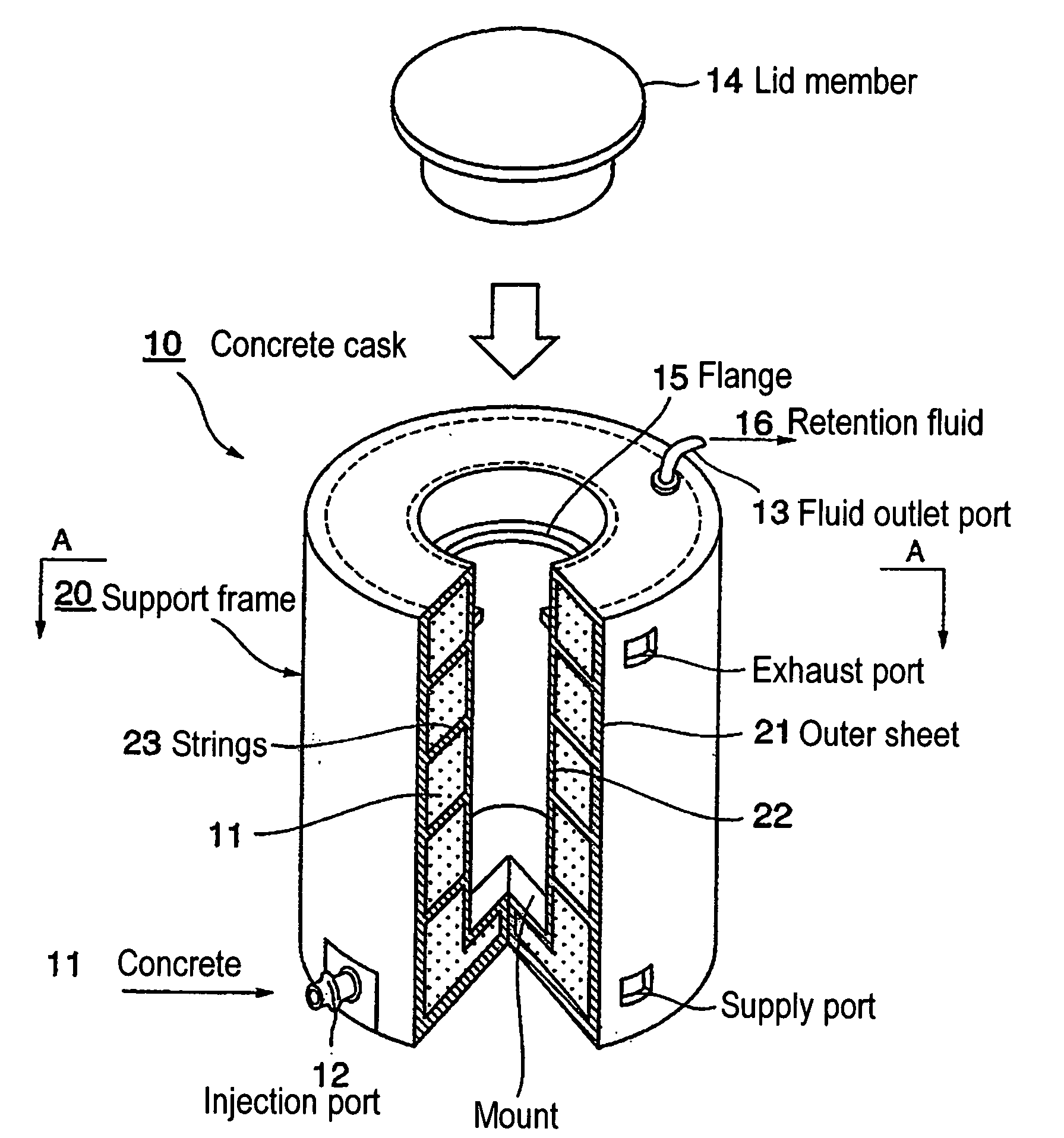
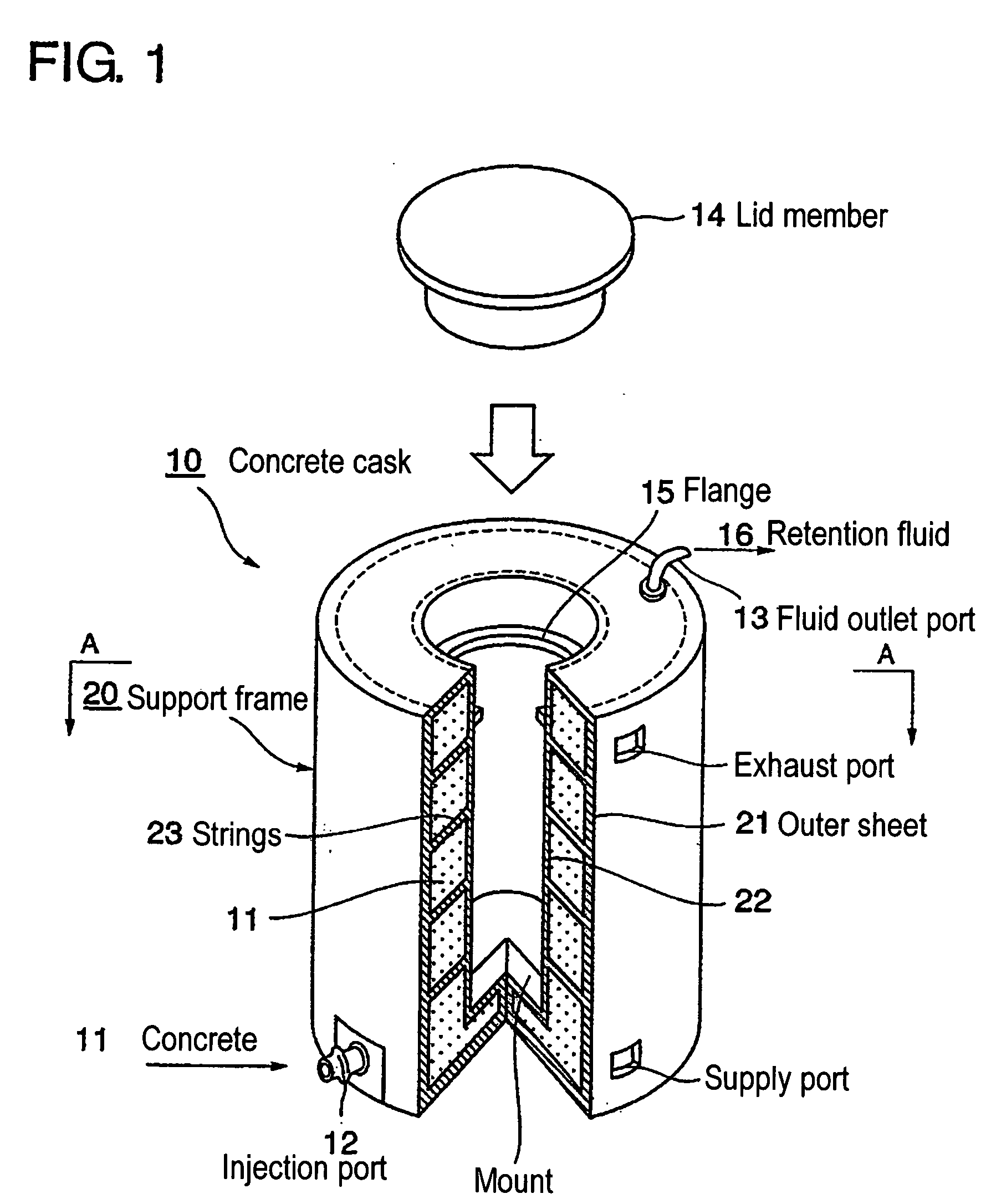
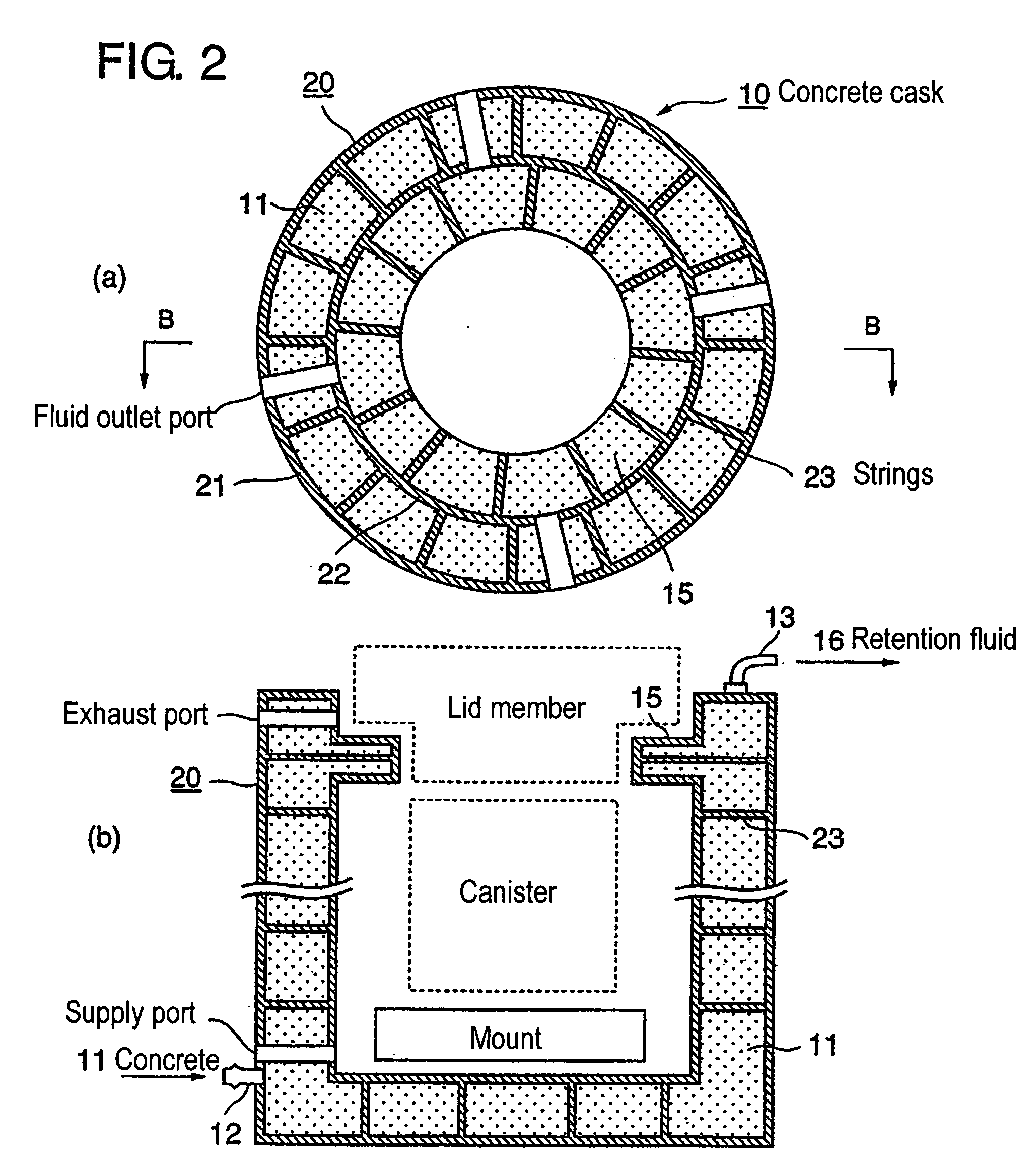
[0034]FIG. 1 shows a perspective view of an embodiment of a fiber reinforced concrete cask according to the present invention; FIG. 2 shows sectional views: (a) a sectional view along line A-A of FIG. 1, and (b) a sectional view along line B-B of FIG. 2(a); and FIG. 3 is a diagram showing the fabrication process for this embodiment of a fiber reinforced concrete cask according to the present invention.

[0035] This embodiment of a fiber reinforced concrete cask would be used as a container to store or transport radioactive material generated in a nuclear power plant such as spent fuel, recyc...


PUM


Abstract

The object of this invention is to provide a fiber-reinforced concrete cask that ensures easy working, enables reducing working cost, excels in strength, durability and heat resistance and enables minimizing cracking; a process for fabrication of the same; and a supporting frame for molding the concrete cask. In particular, concrete cask (10) formed through injecting and solidification of concrete (11) is characterized in that sheets of reinforcement fibers having a thermal expansion coefficient equal to or lower than that of concrete (11) are provided on at least the outer circumferential surface and the inner circumferential surface of the concrete cask (10) and that the inner circumferential surface of outer sheet (21) and the outer circumferential surface of inner sheet (22) are connected with each other by strings of reinforcement fibers (23). Preferably, carbon fibers are used as the reinforcement fibers.

Description

FIELD OF TECHNOLOGY [0001] The present invention relates to a fiber reinforced concrete cask such is used for the transport and storage of radioactive materials, as well as a support frame for molding thereof, and a process for fabrication of the concrete cask. BACKGROUND TECHNOLOGY [0002] When storing or transporting radioactive substances, generated by nuclear power plants such as spent fuel having a high level of radioactivity and decay heat, the container used to hold this material must have a high radioactivity shielding capability, high seal performance, and have adequate cooling capabilities and structural strength. In general, concrete reinforced with steel rods or sheets has been used to fabricate such containers, but problems remain in the current implementations. One of the problems is the difference in the coefficients of thermal expansion between the concrete and the steel reinforcing materials. [0003] Internally or externally reinforcing concrete using steel materials ...

Claims


Application Information

Patent Timeline
IPC IPC(8): G21F5/005G21C19/32G21F5/10G21F9/36
CPCG21F5/005G21Y2002/104G21Y2004/30G21Y2002/302G21Y2002/206
Inventor MORISHIGE, HARUO
Owner MITSUBISHI HEAVY IND LTD
Why Eureka
Try Eureka