Optical transmission apparatus and control method therefor

a transmission apparatus and optical fiber technology, applied in the field of optical transmission apparatuses, can solve the problems of increasing the number of wavelengths physically multiplexed on the optical fiber, affecting the quality of communication, so as to reduce the probability of a change, and ensure the quality of communication

Inactive Publication Date: 2005-09-29
HITACHI LTD
View PDF13 Cites 27 Cited by
  • Summary
  • Abstract
  • Description
  • Claims
  • Application Information

AI Technical Summary

Benefits of technology

[0019] An object of the present invention is to provide an optical transmission apparatus and a control method therefor which can secure satisfactory communication quality by appropriately controlling the power of each signal light not only in a normal state in which neither a loss on the transmission path varies nor the number of multiplexed wavelengths changes, but also in an abnormal state where a loss variation on the transmission path or a change in the number of multiplexed wavelengths has occurred.
[0027] In another embodiment of the invention, the optical transmission apparatus is provided with a supervisory signal light transmitter for generating a supervisory signal light to be transmitted to the optical transmission path of a next section, and the monitor and control unit notifies the occurrence of any loss variation in the preceding section to the following optical transmission apparatus by varying the power of the supervisory signal light outputted from the supervisory signal light transmitter according to the supervisory signal light power outputted from the first means. The notification of any loss variation in the preceding section to the following optical transmission apparatus can also be accomplished by varying the power of the supervisory signal light outputted from the supervisory signal light transmitter according to the signal light power outputted from the optical amplifier. By transmitting any loss variation in the preceding section by varying the power of the supervisory signal light in this way, even if wavelength-division multiplexed signal lights are transmitted to the next section in a wrong state in which power compensation in accordance with loss variations is incomplete, for instance, the next optical transmission apparatus can prevent from mistaking the cause of the occurrence of signal light power variation for a change in the number of multiplexed wavelengths.
[0029] When any loss fluctuation arises on an optical transmission path on which the supervisory signal light and the wavelength-division multiplexed signal lights are carried, both the supervisory signal light and the multiplexed signal lights vary in optical power. However, in the case where the number of multiplexed signal lights (the number of wavelengths) varies on the upstream side, only the power of multiplexed signal lights varies. Using this characteristic in an optical transmission system, the optical transmission apparatus according to the invention judges that, when the supervisory signal light power fluctuates within its permissible range and fluctuations in the wavelength-division multiplexed signal light power deviates from its permissible range, the cause of the fluctuations in the multiplexed signal light power is a change in the number of multiplexed wavelengths, and the automatic output level control by the optical attenuator is restrained.
[0030] According to the invention, therefore, erroneous adjustment of the multiplexed signal light power due to the execution of automatic output level control for the optical amplifier output power can be avoided when the number of multiplexed wavelengths has changed. Further, according to the invention, periodical automatic output level control is executed as long as the supervisory signal light power fluctuates within the permissible range, and forcible optical power automatic output level control is executed for a predetermined period when the supervisory signal light power deviates from its permissible range on account of a loss variation on the transmission path. As a result, the present invention can control the multiplexed signal light output power in accordance with the target value irrespective of the velocity of loss fluctuations, thereby providing an optical transmission system having guaranteed quality of communication.
[0031] In an embodiment of the invention, by executing automatic gain control of the optical amplifier all the time and automatic output level control intermittently for a short period at a time as long as fluctuations in the supervisory signal light power are within the permissible range, the duration of parallel execution of automatic output level control and automatic gain control is minimized. Intermittent execution of automatic output level control for a short period at a time can reduce the probability of a change in the number of multiplexed wavelengths during automatic output level control than in constant execution of automatic output level control as proposed in Non-Patent Reference 1. Therefore, even when the number of multiplexed wavelengths has changed, the occurrence of erroneous adjustment of the multiplexed signal light power can be reduced.
[0032] Further, according to the invention, forcible automatic output level control is carried out for a predetermined period when the supervisory signal light power has deviated from the permissible range, and the automatic output level control is suspended if fluctuations in the multiplexed signal light power deviate from its permissible range during when the automatic output level control is carried out. Accordingly, it is able to reduce the occurrence of erroneous adjustment of the multiplexed signal light power in the event of a change in the number of multiplexed wavelengths even when automatic output level control is taking place.

Problems solved by technology

However, the automatic output level control method described above involves a problem when a difference arises between the number of multiplexed wavelengths, which is the condition for figuring out the total output optical power, and the number of wavelengths of the multiplexed signal lights actually entered into the optical fiber amplifier.
In this case, since each optical fiber amplifier cannot recognize the number of actually multiplexed wavelengths at that moment when the trouble has occurred, matching between the number of wavelengths, which is a precondition for the automatic output level control, and the number of wavelengths physically multiplexed on the optical fiber cannot be achieved.
Therefore, when optical signals of a certain wavelength becomes absent on account of maintenance work or trouble, if automatic output level control of the fiber amplifiers is performed targeting on a total output optical power calculated on the basis of a greater number of signal lights than that of signal lights actually multiplexed, the output optical power per signal light will become higher than the expected level, resulting in a problem that each signal light eventually reaches the receiver at an excessively high input signal level.
On the other hand, any variation in losses is an abnormal event that occurs, for instance, when the maintenance personnel of the optical transmission system pulls or catches the optical fiber, and the varying velocity of losses on the transmission path is supposed to be not less than a few ms.
However, by the above-described method to determine the nature of an event with reference to a frequency threshold, if a variation in the number of wavelengths occurs at a low velocity in or above the ms order, for instance, the variation in total signal power will not be perceived as being consequent on a variation in the number of wavelengths but will be erroneously attributed to a loss variation on the transmission path.
In this case, automatic output level control having as its target value an output optical power of the optical amplifier is selected, resulting in a wrong control operation to increase the signal light power of each wavelength more than required.
Furthermore, whereas two control modes including automatic output level control to compensate for variations in signal power due to loss variations and automatic gain control to compensate for variations in signal power due to variations in the number of wavelengths coexist in the optical amplifier, if it is difficult to identify the cause of variations as mentioned above, the two control modes may be executed at the same time with an adverse effect on signal quality even though one or the other type of variation causes has occurred.
Furthermore, since automatic output level control is always at work according to Non-Patent Reference 1, the optical amplifier may erroneously operate not only when an abnormal event has occurred but also in response to a normal operation by the system administration staff.
According to Patent Reference 1, however, as the control of the optical amplifier is dependent on a specific probe signal light, there is a problem that, if any abnormality of the probe signal light arises for some reason such as a failure in the light source, the optical amplifier will become uncontrollable, inviting a trouble in the transmission of signal lights.

Method used


Image

  • Optical transmission apparatus and control method therefor
  • Optical transmission apparatus and control method therefor
  • Optical transmission apparatus and control method therefor

Examples


first embodiment

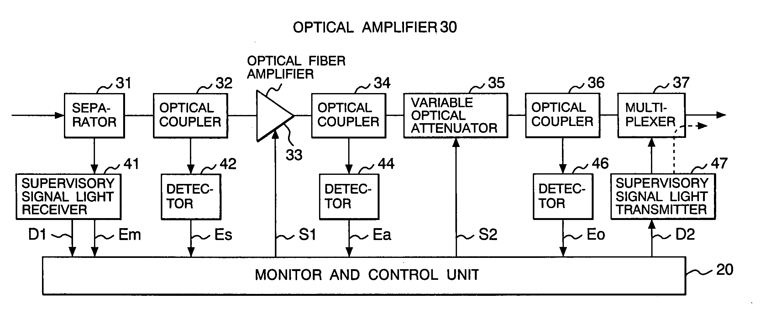
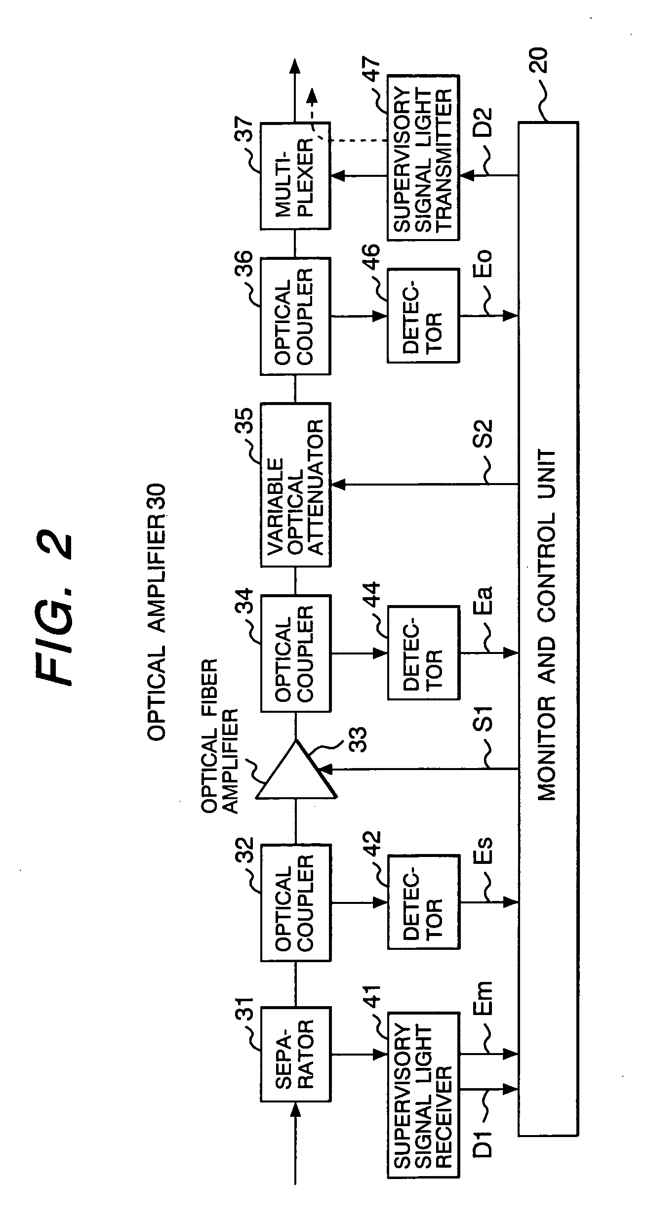
[0053]FIG. 2 shows an embodiment of the optical amplifier 30 to be mounted on the optical transmission apparatuses 1 of FIG. 1.

[0054] The optical amplifier 30 is provided with a separator 31 for separating the supervisory signal light from the optical input to the optical fiber, a first optical coupler 32 for branching part of the signal lights having passed the separator 31, an optical fiber amplifier 33 for optically amplifying signal lights within the signal light wavelength band having passed the optical coupler 32, a second optical coupler 34 for branching part of the output signal lights of the optical fiber amplifier 33, a variable optical attenuator 35 capable of freely adjusting the transmission losses of signal lights outputted from the optical coupler 34, a third optical coupler 36 for branching part of the output signal lights of the optical attenuator 35, a supervisory signal light transmitter 47, and a multiplexer 37 for multiplexing the supervisory signal light outpu...

second embodiment

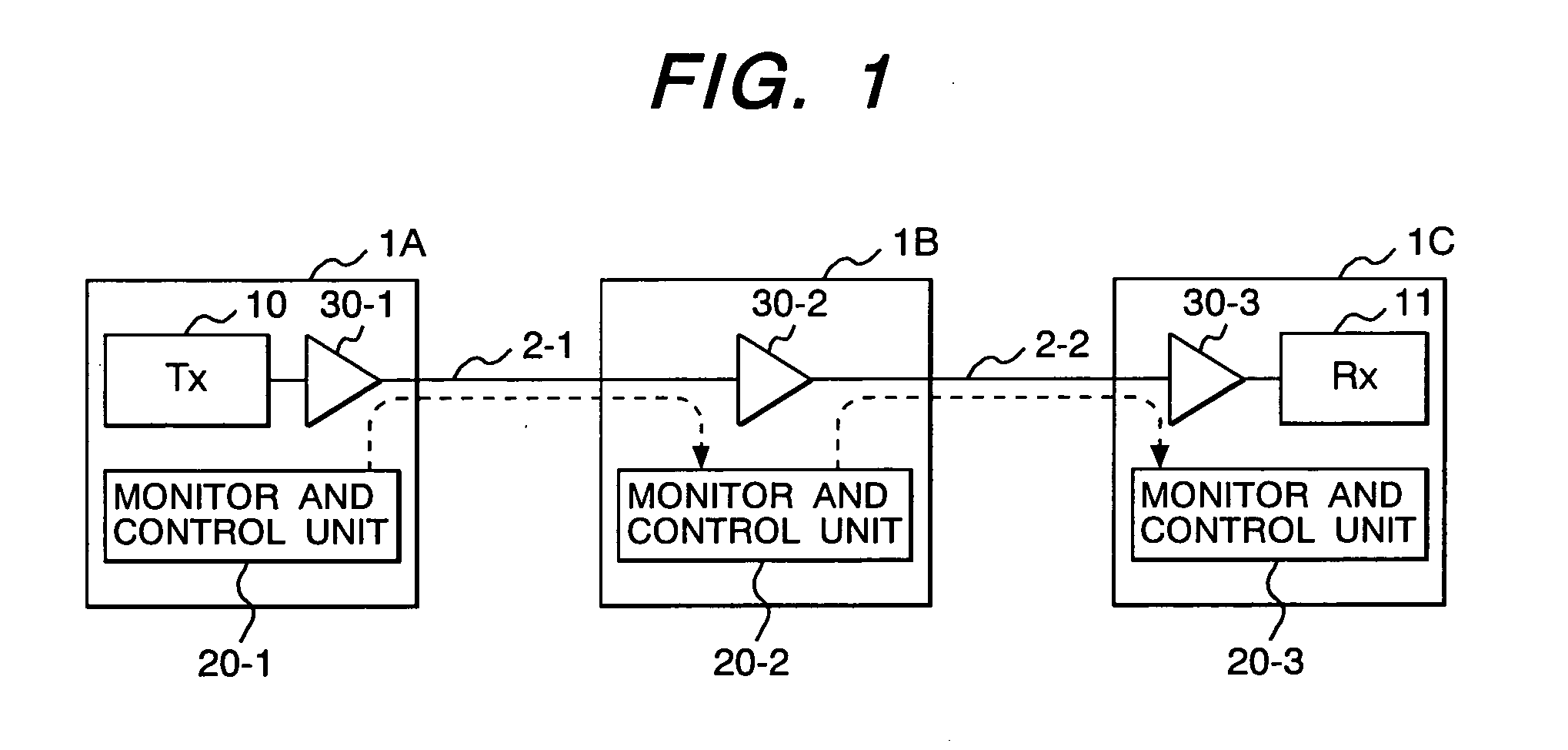
[0087] In the first embodiment described above, as the monitor and control unit 20 terminates the supervisory signal light for every section of the optical fiber and a new supervisory signal light is transmitted to the next section from the supervisory signal light transmitter 47 as shown in FIG. 2, the monitor and control unit 20-3 of the optical transmission apparatus 1C shown in FIG. 1, for instance, cannot detect the presence or absence of any loss variation in the first optical fiber transfer section 2-1 and the extent of loss variation if it occurs. Therefore, when a loss variation occurs in the first optical fiber transfer section 2-1 and a variation is left in the signal light output power Eo because of incomplete compensation for the signal light output power Eo in the optical transmission apparatus 1B for some reason, optical signals manifesting a power variation beyond the permissible range may eventually be relayed to the transfer section 2-2. In this case, the monitor a...

third embodiment

[0092] The third embodiment is characterized in that, in the optical amplifier of FIG. 9, the power of a new supervisory signal light supplied from the supervisory signal light transmitter 47 is varied in proportion to the light power Ea of the amplified signal outputted from the optical fiber amplifier 33.

[0093] In this embodiment, the monitor and control unit 20 varies the control signal S3 according to the amplified signal light power Ea supplied from the detector 44, and the driving bias current of the laser diode 470 of the supervisory signal light transmitter 47 or the extent of attenuation of the optical attenuator 471 is controlled with this control signal S3. According to the embodiment, as the multiplexed signal light power and the supervisory signal light power are varying in association with each other at the time of output from the relaying optical transmission apparatus, there is no fear for the following optical transmission apparatus to mistake any fluctuation in th...


PUM


Abstract

An optical transmission apparatus comprising a first detector for detecting the power of the supervisory signal light separated from received wavelength-division multiplexed signal lights; a second detector for detecting the power of the wavelength-division multiplexed signal lights after the separation of the supervisory signal light; a gain-controlled type optical amplifier for amplifying the wavelength-division multiplexed signal lights; an optical attenuator coupled to the amplifier; and a control unit for controlling the optical amplifier and the optical attenuator so as to keep the output level of the wavelength-division multiplexed signal lights to a predetermined target value, wherein the control unit restrains automatic output level control by the optical attenuator when the supervisory signal light power fluctuates within its permissible range and fluctuations in the signal light power have deviated from its permissible range.

Description

CLAIM OF PRIORITY [0001] The present application claims priority from Japanese application serial No. P2004-089030, filed on Mar. 25, 2004, the content of which is hereby incorporated by reference into this application. BACKGROUND OF THE INVENTION [0002] (1) Field of the Invention [0003] The present invention relates to an optical transmission apparatus and a control method therefor, and more particularly to an optical transmission apparatus and a control method therefor to be used in an optical transmission system which wavelength-division multiplexes a plurality of signal lights and transmits the multiplexed signal lights. [0004] (2) Description of the Related Art [0005] Wavelength-division multiplexing optical transmission for transmitting a plurality of signal lights differing in wavelength bundled into a single optical fiber is generally applied to optical communication systems with a view to increasing the communication capacity and reducing the system cost. In an actual syste...

Claims


Application Information

Patent Timeline
Patent Type & Authority Applications(United States)
IPC IPC(8): H04B10/03H04B10/07H04B10/077H04B10/079H04B10/29H04B10/294H04J14/00H04J14/02
CPCH04B10/00
Inventor UDA, TETSUYANODA, KENTAUCHIYAMA, YASUHIROMASUDA, HIROSHINAKANO, HIROYUKI
Owner HITACHI LTD
Why Eureka
Try Eureka