Systems and methods for controlling flow control devices

a flow control and control device technology, applied in the direction of fluid removal, insulation, survey, etc., can solve the problems of affecting the mechanical and electrical components of such mechanical devices can be prone to sticking, wear and corrosion, and the operating life of the operating well can be much shorter than the life of the production well

Inactive Publication Date: 2005-10-06
CORE LAB CANADA
View PDF16 Cites 60 Cited by
  • Summary
  • Abstract
  • Description
  • Claims
  • Application Information

AI Technical Summary

Benefits of technology

[0013] In another aspect, embodiments of the invention can be used to control a downhole fluid control device such as a pump or valve. In one arrangement, two non-mechanical fluid level sensors are positioned in spaced-apart relation in a wellbore having a water column. The height of the water column is adjusted by selective operation of a downhole pump. During use, a controller operatively coupled to the non-mechanical fluid level sensors determines whether one or both of the non-mechanical sensors are surrounded by water or a gas. After making this determination, the controller alters the operation of the pump (if needed) to bring the height of the water column into a selected range or height. The level sensors can be positioned physically at the operating switch points for the pump (e.g., the upper and lower limits for the height of the water column). Alt

Problems solved by technology

However, because the rate of desorption varies roughly inversely with the exerted hydrostatic pressure, dropping the hydrostatic pressure too low may result in a rate of methane production that can overwhelm the methane recovery equipment.
The mechanical and electrical elements of such mechanical devices can be prone to sticking, wear and corrosion.
Thus, a long-standing and persistent drawback of suc

Method used


Image

  • Systems and methods for controlling flow control devices
  • Systems and methods for controlling flow control devices
  • Systems and methods for controlling flow control devices

Examples


Embodiment Construction

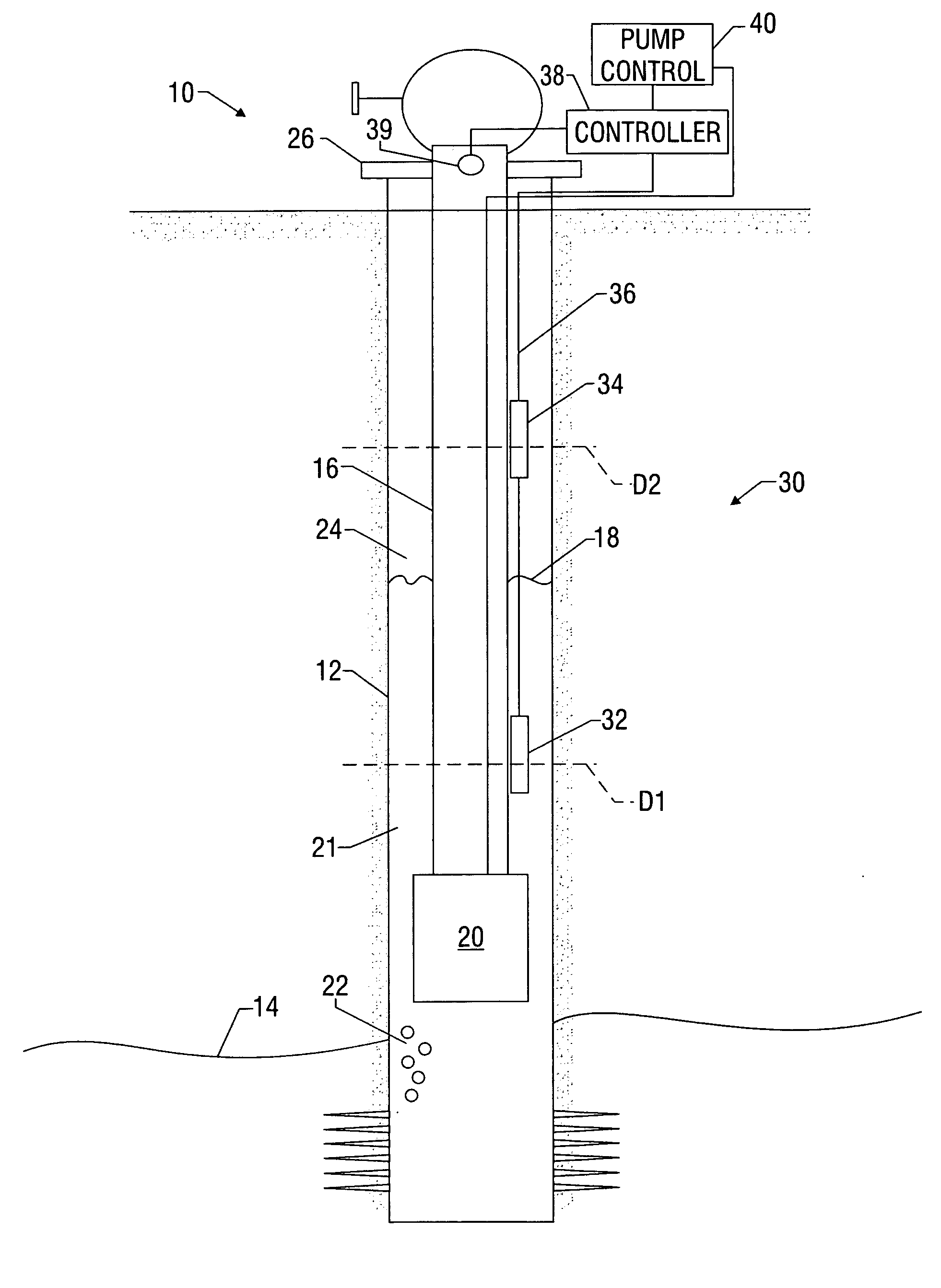
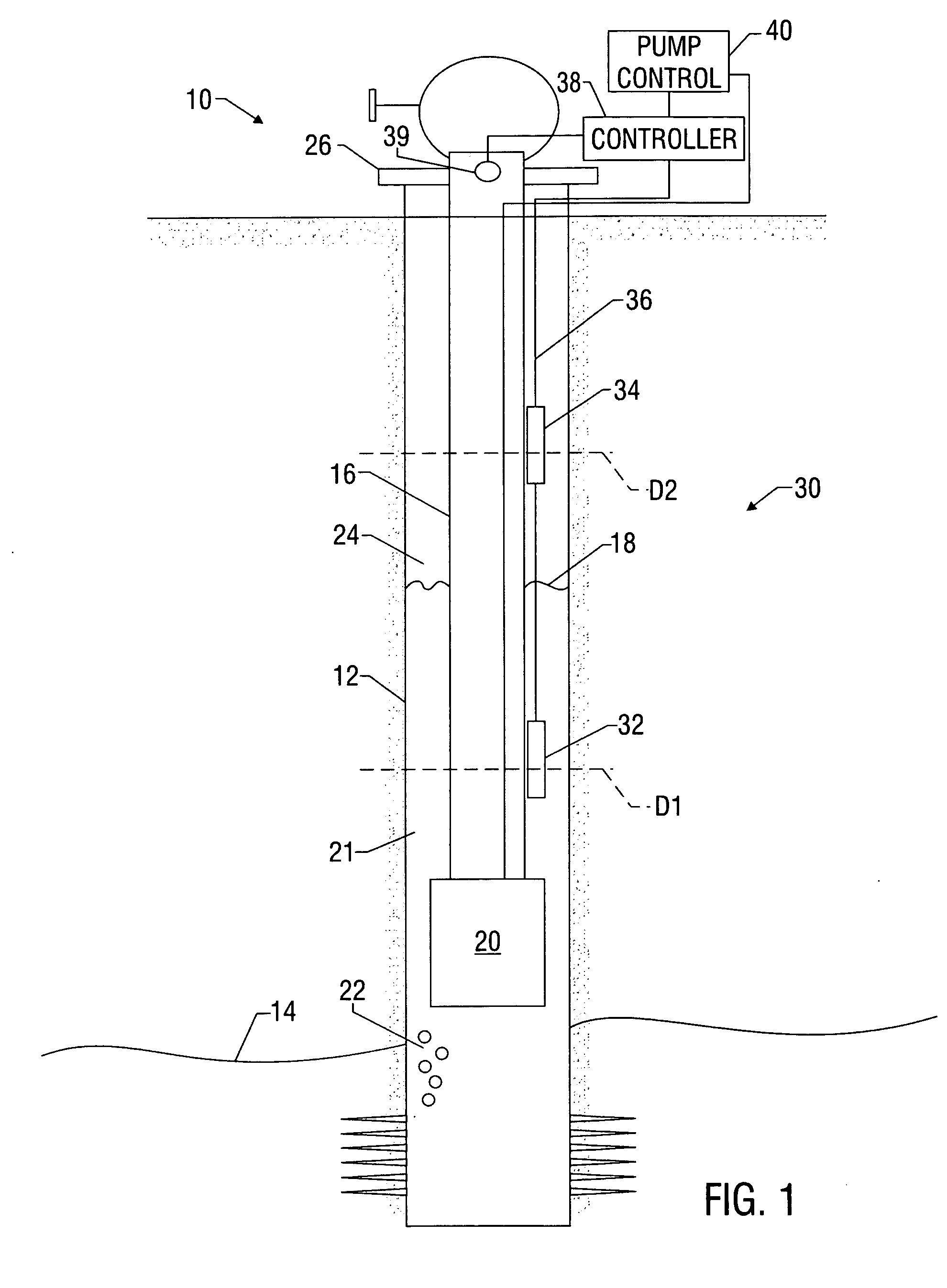
[0023] The present invention relates to devices and methods for controlling equipment, such as pumps, used to recover hydrocarbons (e.g., methane) from subterranean formations. The control systems and methods can apply to any artificial or natural lift technique, including but not limited to gas-lift, PCP pump, ESP pump, rod pump, downhole control valves for selective zone control. The present invention also relates to devices and methods for determining the location of an interface between a first liquid and a second liquid. The present invention is susceptible to embodiments of different forms. There are shown in the drawings, and herein will be described in detail, specific embodiments of the present invention with the understanding that the present disclosure is to be considered an exemplification of the principles of the invention, and is not intended to limit the invention to that illustrated and described herein.

[0024] As will become evident in the discussion below, embodime...


PUM


Abstract

A device for determining a location of an interface between a first fluid and second fluid includes a non-mechanical sensor that measures a selected parameter of interest relating to the fluid surrounding the sensor (“the surrounding fluid”) and a processor for processing the sensor measurements. The non-mechanical sensor measures a parameter relating to the surround fluid without physically co-acting with the surrounding fluid. Exemplary parameters such as thermal properties, electrical properties, fluid properties, and magnetic properties can be measured. The processor is programmed to process the sensor measurements to identify one or more characteristics in the measurements that can indicate the nature of the fluid being measured and thereby determine the location of the interface. The determined location can be used to operate a downhole device such as a pump, to provide real-time monitoring of well conditions, to record data for long-term reservoir characterization, or to actuate an alarm.

Description

CROSS-REFERENCE TO RELATED APPLICATIONS [0001] None. BACKGROUND OF THE INVENTION [0002] 1. Field of the Invention [0003] The present invention relates to control systems and methods for fluid extraction from oil and gas wells. More particularly, the present invention relates to methodologies for controlling a downhole pump in an oil or gas well to optimize the fluid removal process and / or gas, oil, or water production. In another aspect, the present invention relates to systems and devices for optimal control of a flow control device. In yet another aspect, the present invention relates to systems and methods for monitoring and recording physical changes in a fluid body. [0004] 2. Description of the Related Art [0005] Hydrocarbons (e.g., oil and gas) are recovered by drilling a wellbore in a subterranean formation having one or more hydrocarbon reservoirs. Under formation pressure or by artificial lift, the hydrocarbons flow up the wellbore and are recovered at the surface, a proces...

Claims


Application Information

Patent Timeline
IPC IPC(8): E21B43/00E21B47/00E21B47/04G01F23/22G01F23/24G01N13/00
CPCE21B43/006E21B47/0007G01F23/247G01F23/22E21B47/042E21B47/008E21B47/047
Inventor JABUSCH, KIRBYBUSSIERE, COLIN
Owner CORE LAB CANADA
Why Eureka
Try Eureka