Arrangement and method for coupling an air compressor to the driving shaft of an internal combustion engine

Active Publication Date: 2005-10-06
MAN NUTZFAHRZEUGE AG
View PDF4 Cites 5 Cited by
  • Summary
  • Abstract
  • Description
  • Claims
  • Application Information

AI Technical Summary

Benefits of technology

[0014] The use of a controllable turbocoupling as a gearing element between the crankshaft of the internal combustion engine and the air compressor makes it possible, in an advantageous manner, to connect the air compressor as necessary without any sudden fluctuations in torque, and as a consequence thereof sudden slight accelerations or decelerations or sudden changes of the noise level of the internal combustion engine, being noticeable.
[0015] Particularly advantageous is the use of a so-called filling or charge controlled turbocoupling, because as a result a precise increase or reduction of the torque transferred by the turbocoupling is possible.
[0016] The rotatable mounting of the pump impeller on the shaft that is operatively connected with the air compressor, or, particularly advantageously, on the turbine wheel that is connected with this shaft so as to be fixed against rotation relative thereto, enables a particularly compact construction of the inventive arrangement. Such an arrangement can be selectively embodied as a simple turbocoupling having only one fluid chamber system concentrically disposed in the turbine wheel and pump impeller, or, where there is a requirement that an increased moment can be transferred, as a dual turbocoupling having two fluid chamber systems concentrically disposed in the turbine wheel and pump impeller.
[0018] In this connection, it is particularly advantageous if a toothing is provided on the outer periphery of the pump impeller, which toothing on the one hand meshes with a pinion driven by the driving shaft, and on the other hand meshes with the drive pinion of the further auxiliary device, because in this manner the function of the turbocoupling can advantageously be integrated into a gear wheel of a drive chain, and due to the drive moment required by the auxiliary devices already avoids the problem of the tooth surface impact due to the air compressor.
[0020] The arrangement for coupling the air compressor is advantageously operated pursuant to a method that on the one hand connects the turbocoupling as a function of the pressure in the compressed air system, which contributes to a minimization of the fuel requirement, and on the other hand controls the filling of the turbocoupling such that the air compressor can transfer no noticeable negative torque, in other words a torque counter to the drive direction of rotation of the air compressor that is effected by back expansion in the compression chamber of the air compressor. In addition to a design of the fluid chambers that is optimized for this purpose, this can be advantageously achieved in that the turbocoupling is either operated permanently, or particularly advantageously only if the negative torque occurs, with enough slip that a transfer of this negative torque does not take place due to the turbocoupling.

Problems solved by technology

Although such arrangements have a simple construction, they do not take into account the minimization of fuel consumption demanded these days, and in addition have the drawback that the characteristic, which results with the reciprocating piston air compressors that are used, of exerting a negative torque, after passing the upper dead center position, due to back expansion, leads to the lifting of the tooth surfaces of prearranged toothed-wheel gearings.
This shifting of the tooth surfaces, in turn, is responsible for an extremely undesirable development of noise, and increases the wear of the gears that are involved.

Method used


Image

  • Arrangement and method for coupling an air compressor to the driving shaft of an internal combustion engine
  • Arrangement and method for coupling an air compressor to the driving shaft of an internal combustion engine
  • Arrangement and method for coupling an air compressor to the driving shaft of an internal combustion engine

Examples


Embodiment Construction

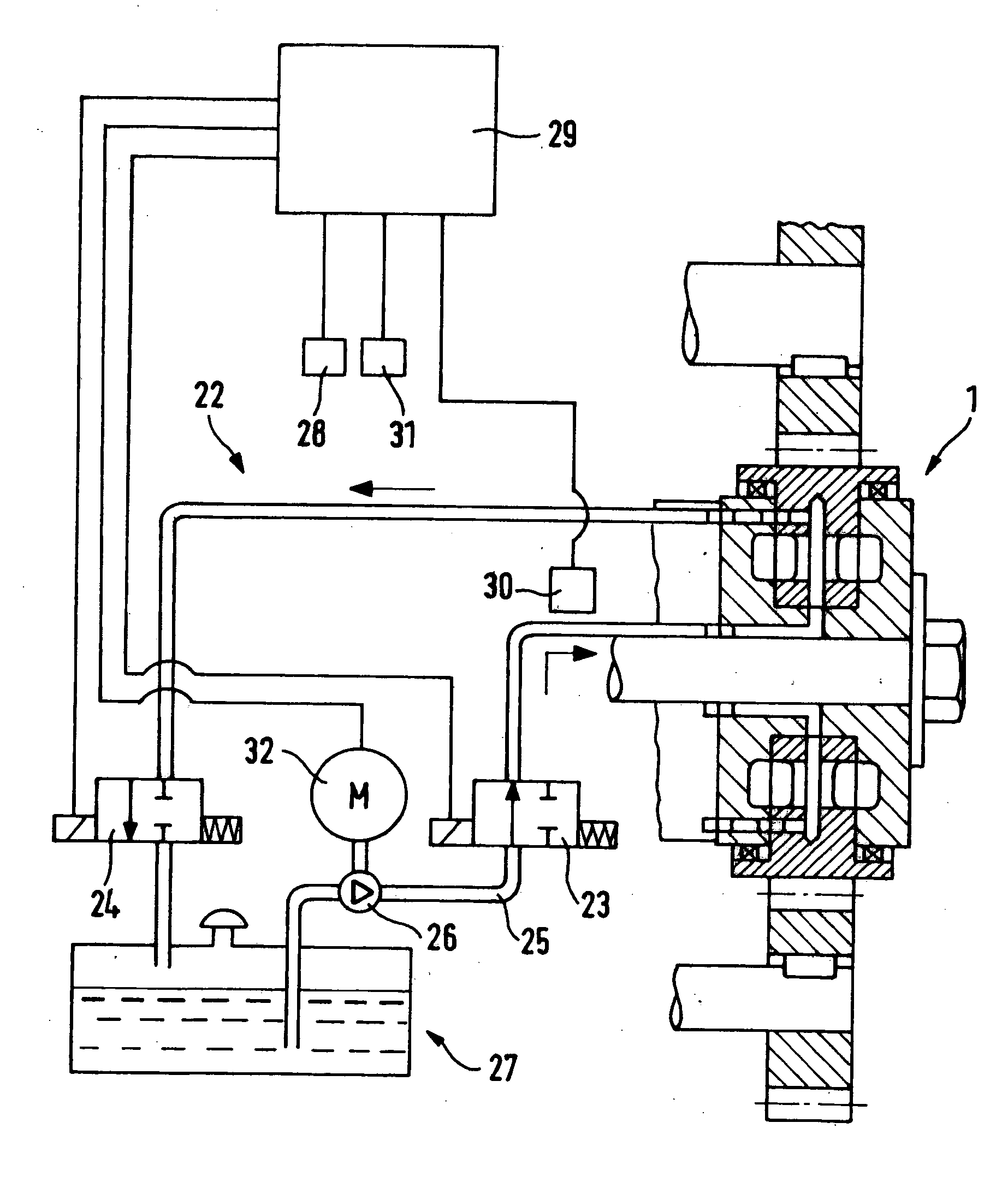
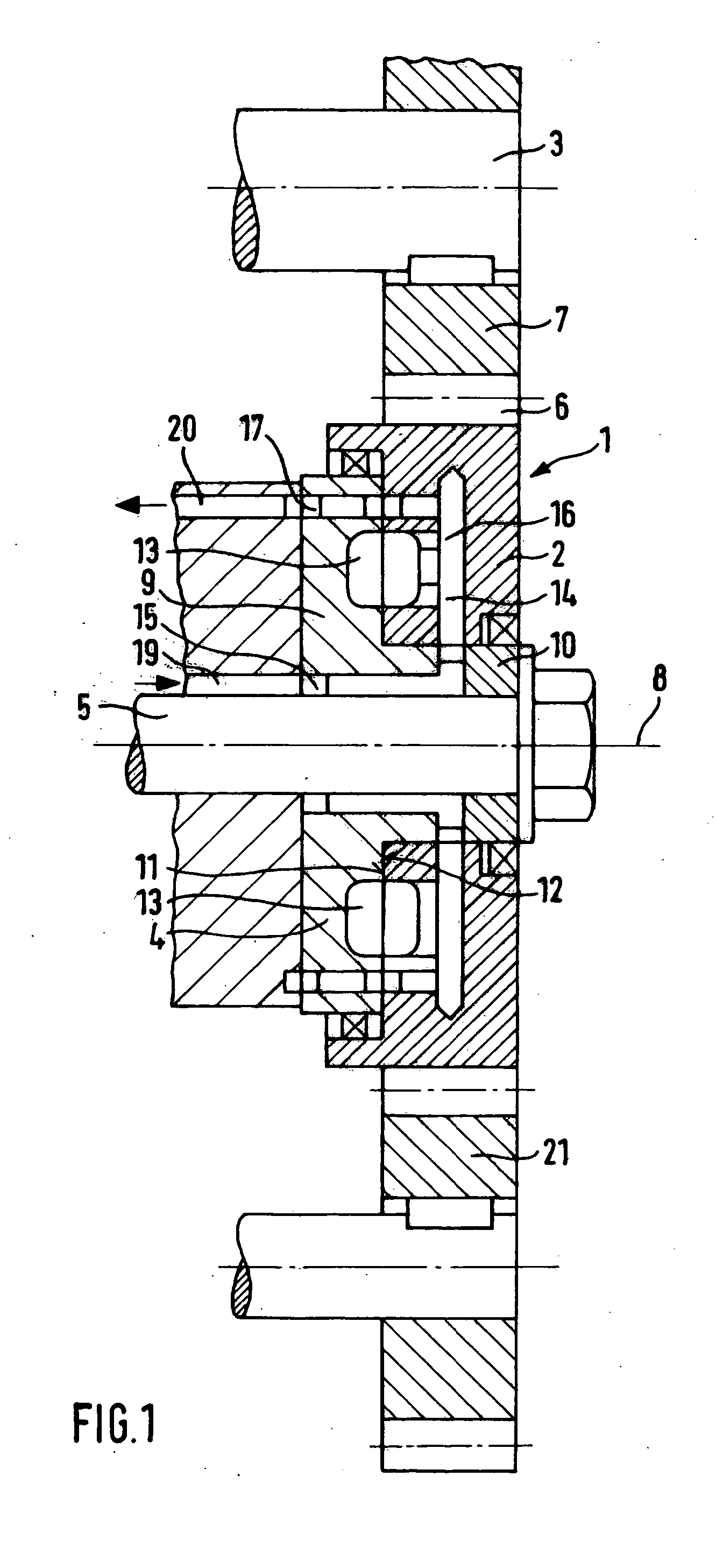
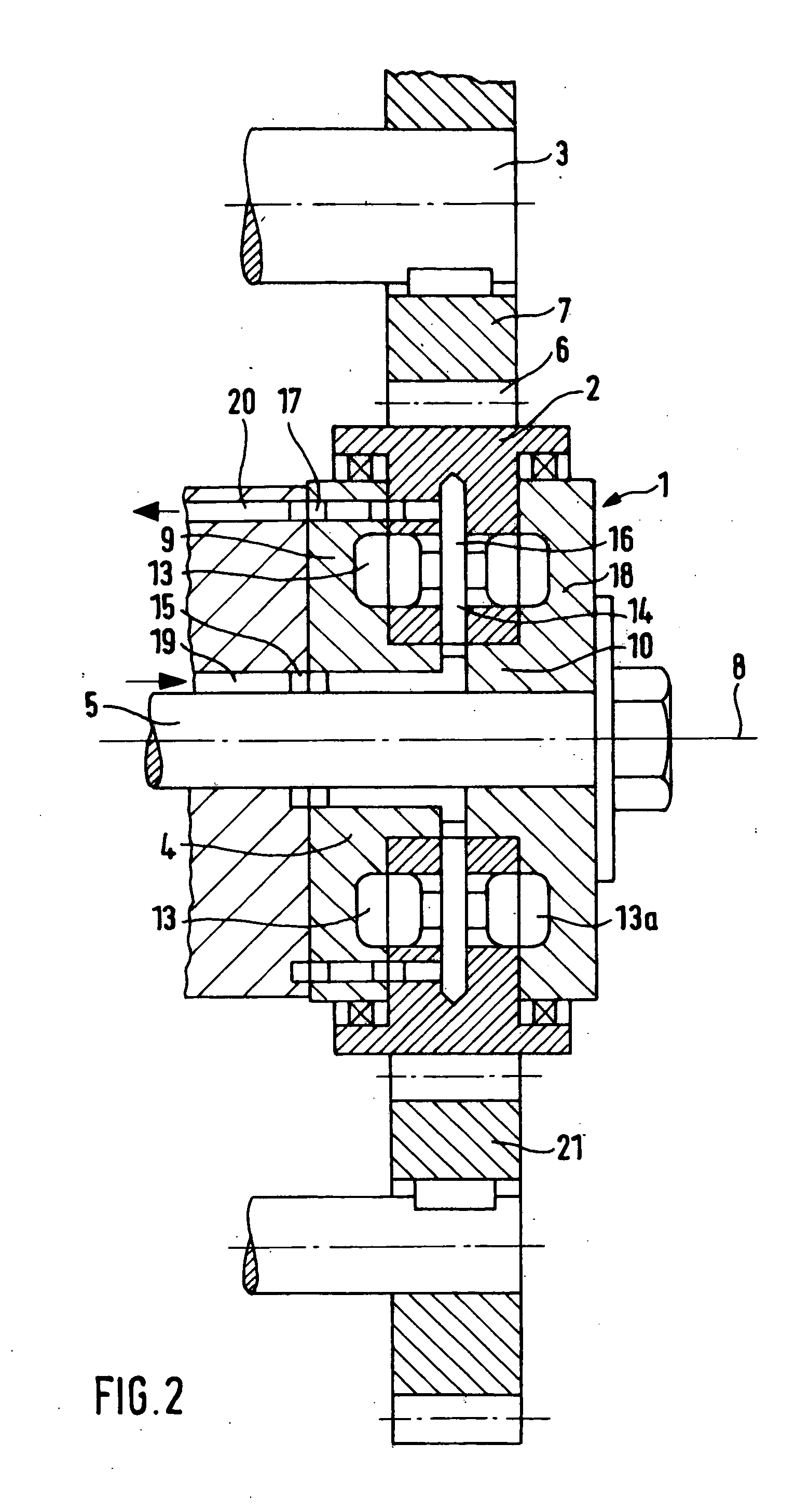
[0022] Referring now to the drawings in detail, provided for driving an air compressor is, as schematically illustrated in FIG. 1, a turbine-driven coupling or turbocoupling 1, the turbine wheel 4 of which is seated on the shaft 5 that operates the air compressor (not illustrated) so as to be fixed against rotation relative thereto. The turbine wheel 4 is provided with a first portion 9 having a large diameter, and a second portion 10 having a small diameter. The pump impeller or rotor 2 of the turbocoupling 1 is embodied as an annular body of rotation and, via its inner diameter, rotatably rests upon the second portion 10 of the turbine wheel 4 in such a way that the facing lateral surfaces 11, 12 of the turbine wheel 4 and of the pump impeller 2 directly adjoin one another. Disposed in the turbine wheel 4 and the pump impeller 2, concentrically relative to the axis of rotation 8 and essentially in halves, with their halves being disposed opposite one another, are fluid chambers 13...


PUM


Abstract

An arrangement and method for coupling an air compressor to the driving shaft of an internal combustion engine that is used as the drive engine of a vehicle, wherein the air compressor supplies a pneumatic device. The arrangement contains a controllable turbocoupling, the pump impeller of which can be driven by the driving shaft of the internal combustion engine and that, by means of a fluid in the form of a working medium, drives the turbine wheel that in turn is operatively connected with the shaft of the air compressor that is to be operated.

Description

BACKGROUND OF THE INVENTION [0001] The present invention relates to an arrangement for coupling or connecting an air compressor to the driving shaft of an internal combustion engine that is used as the drive engine of a vehicle, wherein the air compressor supplies a pneumatic device; the invention also relates to a method of operating such an arrangement. [0002] With vehicles that are common these days, and which have pneumatic devices, the air compressor is coupled directly with the driving shaft of the internal combustion engine via appropriate gearing arrangements. [0003] The quantity of air delivered from the air compressor to the pneumatic device is regulated by excess pressure valves that are disposed in the pneumatic device in such a way that when a maximum pressure is exceeded, the excess air escapes via the indicated excess pressure valves. [0004] Although such arrangements have a simple construction, they do not take into account the minimization of fuel consumption demand...

Claims


Application Information

Patent Timeline
IPC IPC(8): F02B33/00F02B33/44F16D33/06F16D33/16G01H1/00G01H1/12G01M7/02G01N29/14G01N29/28G10K11/22
CPCF16D33/06F16D33/16G10K11/22G01N29/14G01N29/28G01H1/12
Inventor MOLLER, HERIBERT
Owner MAN NUTZFAHRZEUGE AG
Why Eureka
Try Eureka