Floating ball check valve

Active Publication Date: 2005-10-06
PARKER INTANGIBLES LLC
View PDF14 Cites 50 Cited by
  • Summary
  • Abstract
  • Description
  • Claims
  • Application Information

AI Technical Summary

Benefits of technology

[0011] Accordingly, in order to overcome the deficiencies of the prior art devices, the present invention provides an improved floating ball check valve that utilizes a generally ring-shaped seat of a non-resilient plastic material, such as a thermoplastic or fluoroplastic material, for example that can be molded or machined without requiring coining thereof. These sea

Problems solved by technology

Many check valve designs limit the bias force of the ball or poppet against the seat since excessive force can damage the elastomeric material and cause the valves to leak.
However, elastomeric seals are limited in application, typically by either degradation, caused by chemical attack, or extreme low or high operating temperatures.
However, thermoplastic materials, unlike elastomeric materials, are not resilient and therefore are not well suited to provide for reliable dynamic seals.
However, thermoplastic materials also have high coefficients of thermal expansion and low compressive yield strengths that decrease rapidly with increasing operating temperatures.
They also deform permanently, over time, at stress levels well below their yiel

Method used


Image

  • Floating ball check valve
  • Floating ball check valve
  • Floating ball check valve

Examples


Embodiment Construction

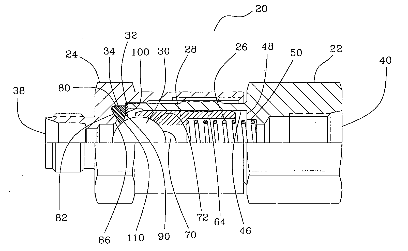
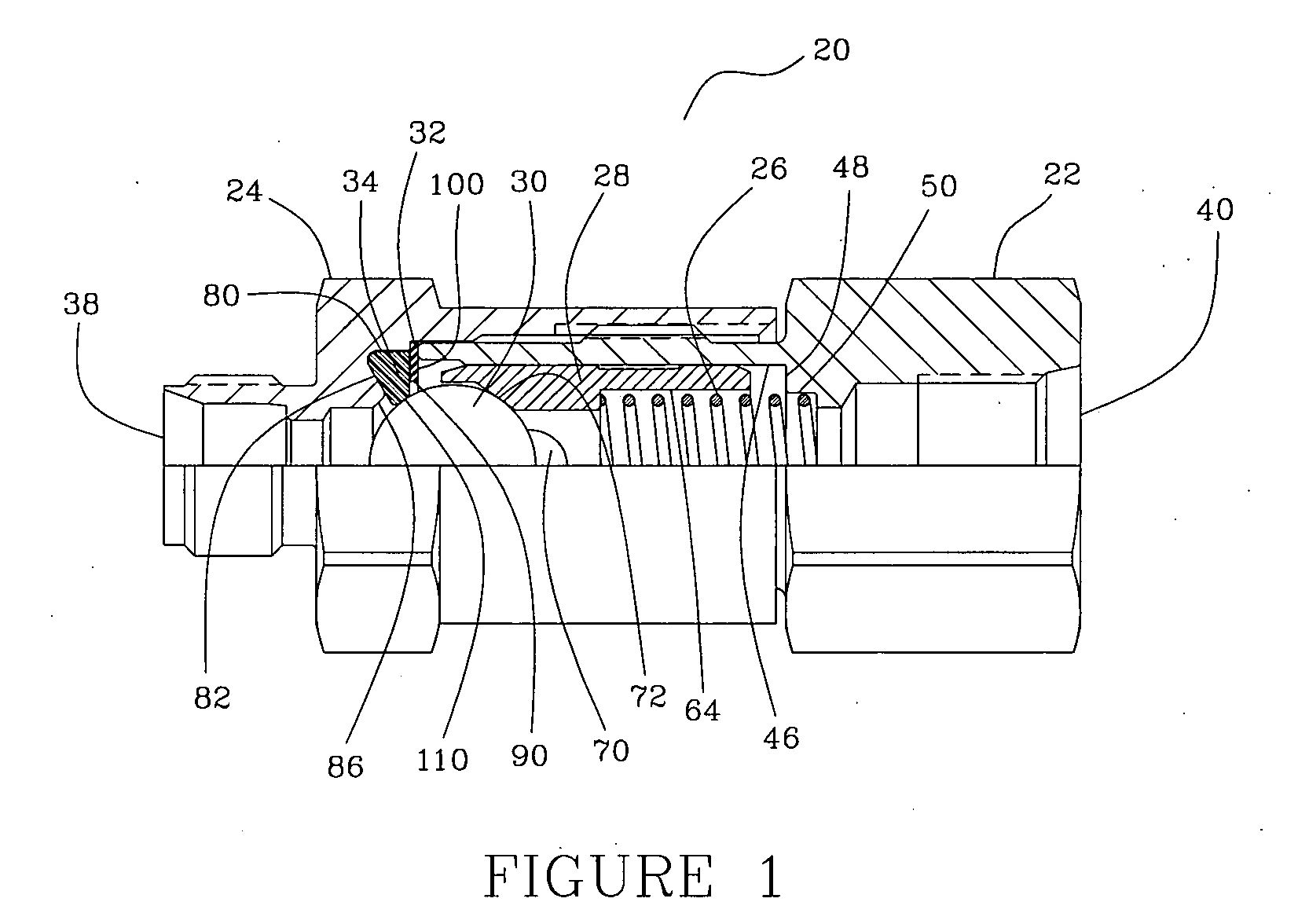
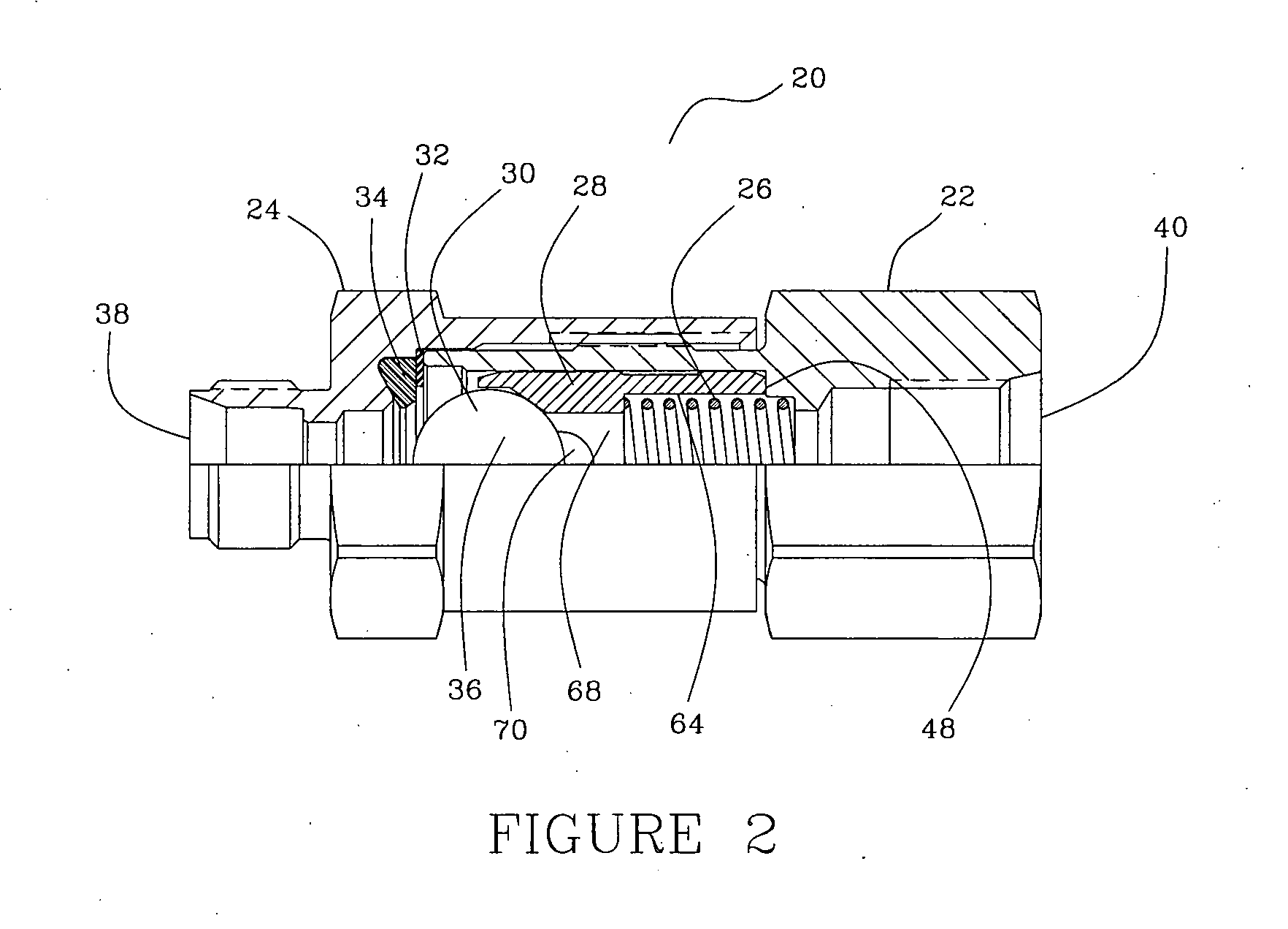
[0039] Referring now to the several drawings, illustrated in FIG. 1 is a partial longitudinal cross section of the floating ball check valve, generally indicated at 20, showing check valve 20 in the closed position, i.e., showing the locations of the axially movable components when the biasing force exceeds the upstream pressure, thereby preventing pressurized fluid flow through check valve 20. FIG. 2 is a view, similar to that of FIG. 1, but showing check valve 20 in the open position, i.e., when the upstream fluid pressure exceeds the biasing force, thereby allowing pressurized fluid to flow through check valve 20. As best illustrated in FIGS. 1 and 2, ball check valve 20 includes a valve body 22, a valve cap 24, a bias spring 26, a ball guide 28, a sealing ball 30, a seat retainer 32 and a seat 34. In addition, check valve 20 is provided with an inlet port 38 and an outlet port 40, with the flow through check valve 20 being unidirectional from inlet port 38 to outlet port 40.

[00...


PUM


Abstract

In an improved floating ball check valve including a body having an outlet port, a cap, having an inlet port, joined with the body, a ball guide slidably received within the body and having a ball pocket for receiving a sealing ball, a biasing spring for biasing the ball toward the inlet port, an annular seat retainer in the cap and a generally ring-shaped seat, of non-resilient plastic material of preferably thermoplastic or fluoroplastic composition, substantially received within a conical bore within the cap and retained therein via the seat retainer, with the spherical surface of the ball being urged into a sealing engagement with an arcuate/spheric sealing surface of the seat having a radius slightly larger than the radius of the sealing ball, with the noted seat materials and geometries permitting seat self-compensation for pressure and temperature. An improved manufacturing method is also set forth.

Description

CROSS-REFERENCE TO RELATED CASES [0001] The present application claims the benefit of the filing date of U.S. Provisional Application Ser. No. 60 / 557,652, filed Mar. 30, 2004, the full disclosure of which is incorporated herein by reference.FIELD OF THE INVENTION [0002] The present invention generally relates to check valves, particularly to floating ball check valves with replaceable thermoplastic valve seats having specific curved seat surfaces that mate with spherical radii of associated sealing balls, thus permitting self-compensation for pressure and temperature. BACKGROUND OF THE INVENTION [0003] Check valves are routinely used to permit fluid flow in but one direction, with two common types thereof being the ball check valve and the poppet valve. Both types may include a spring to bias the sealing member, either the ball or the poppet, against the valve seat to maintain a seal until the upstream fluid pressure, acting against the sealing member, exceeds the spring force to un...

Claims


Application Information

Patent Timeline
IPC IPC(8): F16K15/04
CPCF16K15/044Y10T137/0491Y10T137/6086Y10T137/7928
Inventor DOUTT, MICHAEL L.
Owner PARKER INTANGIBLES LLC
Why Eureka
Try Eureka