Method for stimulation of liquid flow in a well

a well and liquid flow technology, applied in the field of water wells, can solve problems such as potential danger, and achieve the effects of less co2, effective and efficient, and better manipulation of materials

Inactive Publication Date: 2005-10-06
SUBSURFACE TECH INC
View PDF9 Cites 19 Cited by
  • Summary
  • Abstract
  • Description
  • Claims
  • Application Information

AI Technical Summary

Benefits of technology

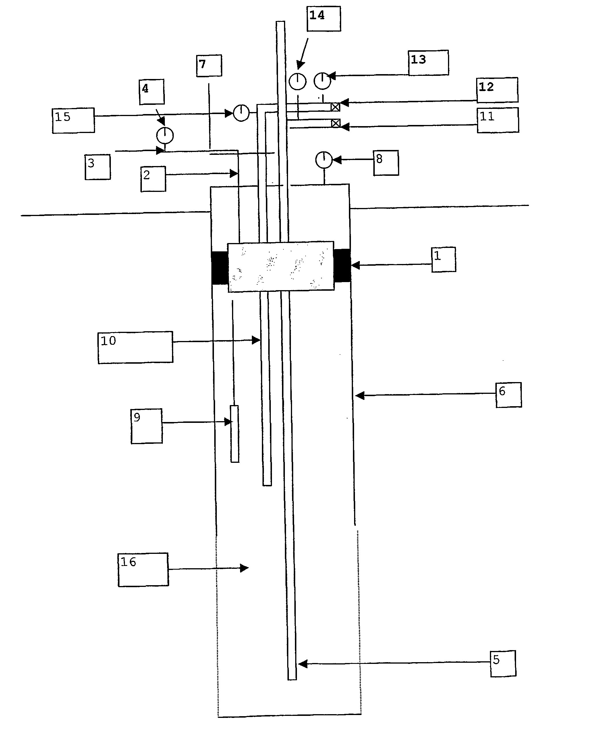
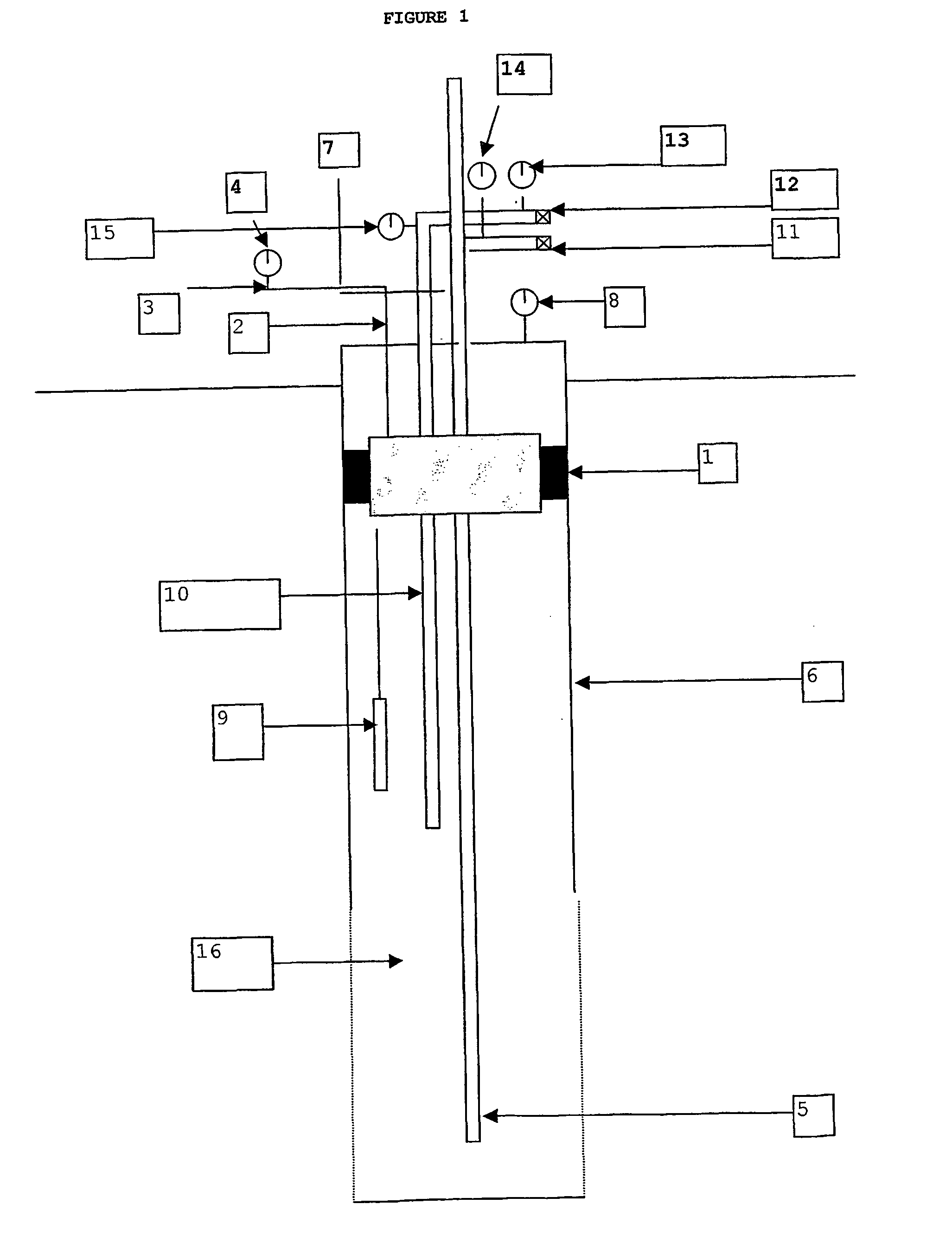
[0015] Monitoring various physical and chemical reactions inside the well during injection of gaseous and liquid CO2, such as disclosed in U.S. Pat. No. 5,394,942, allows better manipulation of and control over the materials during such a process. For example, the use of telemetry to monitor pressure and temperature during the entire process on a well allows data collection for quality control and potential improvements. It is also possible to incorporate direct and continuous monitoring of such parameters as pH, total dissolved solids, conductivity, CO2, etc. This would allow the refinement of the process to make it more effective as well as more efficient, such as indicating the efficient use of less CO2, and concomitant lowering of injected CO2 levels, during the process.
[0016] The most important aspect of injecting CO2 into a water well is to inject enough liquid or gaseous CO2 into the well and the surrounding formation without excessive freezing of the water in the well through the phase changes of vaporization (liquid to gas), freezing (liquid to solid), and sublimation (solid to gas) . It is the energy delivered during these phase changes that allows the surfaces of a well and the surrounding aquifer to be effectively cleaned of deposits. To prevent freezing, the first part of the process is the injection of gaseous CO2 for a long enough period of time to evacuate water from both the well and from a certain distance into the formation. This could be described as a bubble into which liquid CO2 is then injected. After some of the water is evacuated, liquid CO2 is then introduced into the sealed well, most often in short pulses, while still feeding gaseous CO2. The pulses are short for the purpose of determining how a well will respond to the injection of the additional energy. It is very important to observe the various pressures during the stages of liquid CO2 injection. Additionally, in the event that the hydrostatic pressure or the pressure inside the well during injection is greater than 75 psi, intermittent pulses of a negative pressure vacuum can stimulate the formation of solid CO2. Finally, it is important to prevent the phase change from liquid CO2 to solid CO2 inside the injection lines, as this can cause spiking of the pressure gauges and also create a potentially dangerous situation with trapping of liquid CO2. This is prevented by maintaining a pressure of greater than 75 psi in the injection lines.

Problems solved by technology

Finally, it is important to prevent the phase change from liquid CO2 to solid CO2 inside the injection lines, as this can cause spiking of the pressure gauges and also create a potentially dangerous situation with trapping of liquid CO2.

Method used


Image

  • Method for stimulation of liquid flow in a well
  • Method for stimulation of liquid flow in a well

Examples


Embodiment Construction

[0018] Prior to any work to be performed to increase the output of a dry or inefficient well, it is necessary to evaluate the aquifer and the type of problem in the well. This is so because every well is slightly different from any other well in terms of physical characteristics and properties and the type of problems presented in water flow. Additionally, the amount of injection of energy during the process disclosed in U.S. Pat. No. 5,394,942 can vary depending upon well design, well problems, well construction, and site considerations. Hence, before any type of work is to be done on a dry or inefficient well, the practitioner is to gather information about the history and characteristics of the well. Such evaluative information is contained within geophysical logs or drillers logs, analysis of the chemistry of the water contained within the well, analysis of the groundwater microbiology, downhole video images, and from other information sources that may exist. By proper informati...


PUM

PropertyMeasurementUnit
pressureaaaaaaaaaa
pressureaaaaaaaaaa
pressureaaaaaaaaaa

Abstract

An improved method of controlled energy delivery utilizing solid, liquid, and gaseous carbon dioxide (CO2) into a water well and the surrounding aquifer to remove deposited material which may cause loss of capacity in wells and a variety of water quality problems. After proper study and evaluation of problems associated with a well to be treated, adequate injection of the required amount of CO2 and energy is achieved by real-time monitoring during the injection and manipulating the phase changes in the CO2 that take place in the well and the aquifer.

Description

CROSS-REFERENCE TO RELATED APPLICATIONS [0001] This application claims priority from Mansuy, “Aqua Freed Process,” U.S. Provisional Application No. 60 / 254,149, filed Dec. 8, 2000, herein incorporated by reference.BACKGROUND OF THE INVENTION [0002] 1. Field of the Invention [0003] This invention relates to water wells, and more particularly to an improved method of removing deposited material from a well and the surrounding aquifer. This method generally comprises initially properly evaluating problems associated with a particular well and then utilizing the controlled and telemetry-monitored injection into the well of energy derived from phase changes in solid, gaseous, and liquid carbon dioxide (CO2) to remove such deposited material. [0004] 2. Description of the Prior Art [0005] The prior art reveals techniques for stimulating the flow of water in a dry well or one providing insufficient water. For example, in U.S. Pat. No. 5,394,942 issued to Catania, et al., the disclosures of w...

Claims


Application Information

Patent Timeline
Patent Type & Authority Applications(United States)
IPC IPC(8): C02F1/68C09K8/50C09K8/594E21B33/13E21B37/00E21B43/25
CPCC09K8/50E21B43/255E21B37/00C09K8/594
Inventor MANSUY, NEIL
Owner SUBSURFACE TECH INC
Why Eureka
Try Eureka