Lock chamber device for vacuum treatment unit and procedures for its operation

a vacuum treatment unit and lock chamber technology, applied in mechanical equipment, machines/engines, radial flow pumps, etc., can solve the problems of inability to use the apparatus in large volume lock chambers, etc., to improve the operation efficiency of lock chamber units, shorten evacuation times, and shorten the cycle time of lock chamber units

Inactive Publication Date: 2005-10-06
APPLIED MATERIALS GMBH & CO KG
View PDF12 Cites 19 Cited by
  • Summary
  • Abstract
  • Description
  • Claims
  • Application Information

AI Technical Summary

Benefits of technology

[0014] It is, thus, a task of the present invention to improve the operational efficiency of a lock chamber unit for vacuum coating plants, especially of the existing 5-chamber or 7-chamber systems, respectively, being thus improved with two, up to three, load and unload lock chambers, as well as with a process chamber, and especially achieving shorter evacuation times and ...

Problems solved by technology

However, the apparatus is only suitable for lock chambers having a small volume, and for processes where the processing period is long compared wi...

Method used


Image

  • Lock chamber device for vacuum treatment unit and procedures for its operation
  • Lock chamber device for vacuum treatment unit and procedures for its operation
  • Lock chamber device for vacuum treatment unit and procedures for its operation

Examples


Embodiment Construction

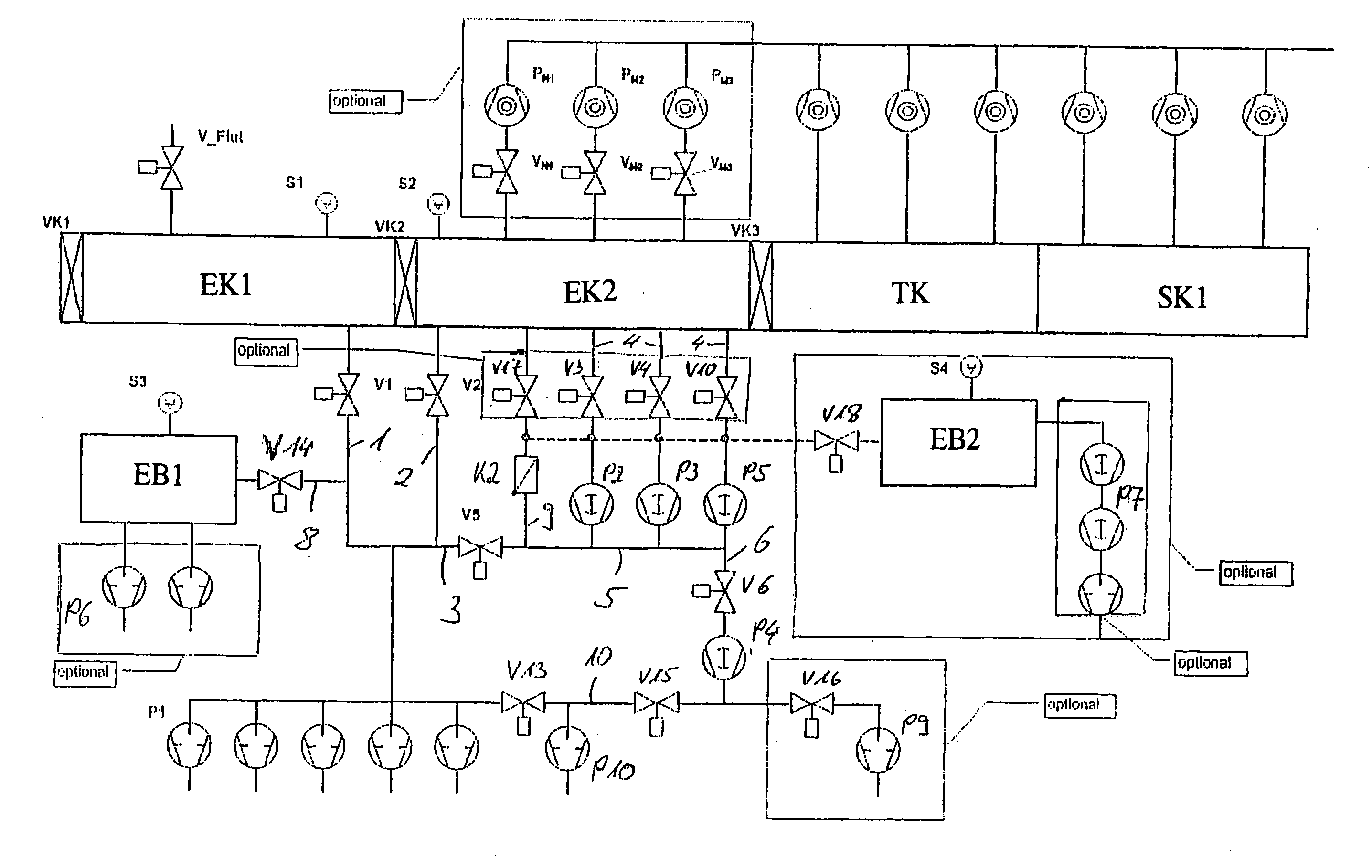
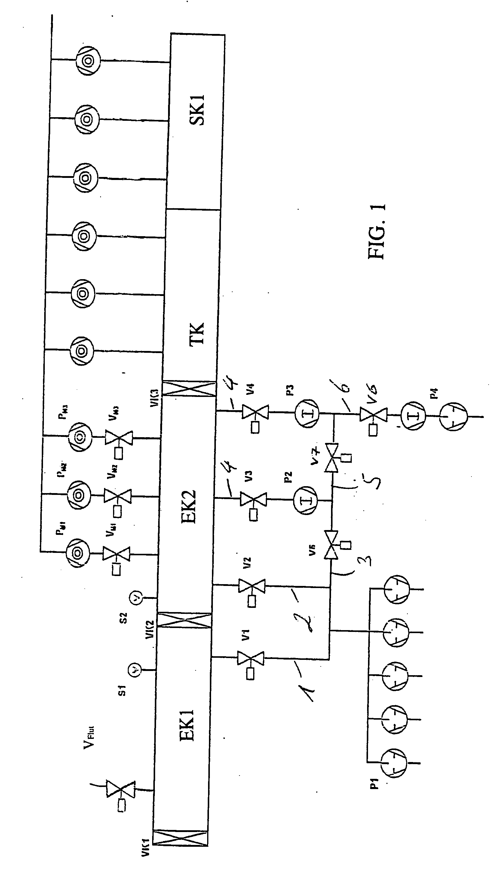
[0035]FIG. 1 features a schematic representation of the inlet section of a vacuum treatment plant, in the present case a glass coating plant, with two inlet chambers EK1 and EK2, as well as a transfer chamber TK and a sputtering chamber SK1. The sputtering chamber SK1 and the transfer chamber TK feature a plurality of high-vacuum pumps, in order to adjust high-vacuum conditions for the coating area.

[0036] The inlet chambers EK1 and EK2 are separated against the outer environment by means of valve flap VK1, and against said transfer chamber TK by means of valve flap VK3. Amongst said devices, separation is being produced by valve flap VK2.

[0037] A valve VFlut for ventilating said inlet chamber EK1 is provided at said inlet chamber EK1.

[0038] Additionally, at inlet chamber EK1, a first pump set P1 is provided with five parallel integrated rotary vane pumps, connected with inlet chamber EK1 over conduit 1 and valve V1. Furthermore, pump set P1 is connected with inlet chamber EK2 thr...


PUM

PropertyMeasurementUnit
Pressureaaaaaaaaaa
Volumeaaaaaaaaaa
Areaaaaaaaaaaa

Abstract

A multistage lock chamber device with at least two lock chambers, a first pump set for evacuating a first lock chamber, and a second pump set for evacuating a second lock chamber. The first pump set (P1) may evacuate both the first and the second lock chamber, or both jointly. The first pump set may also be utilized as a prior pumping stand of the second pump set. Additionally, an integrated third pump set can be utilized as a pre-pumping stand for the second pump set and/or first pump set. Alternately or additionally, the device can include at least one buffer unit, whose buffer volume is being utilized to produce a sudden decline in pressure inside the lock chamber by means of pressure equalization.

Description

CROSS-REFERENCE TO RELATED APPLICATION [0001] This application claims priority to European Patent Application No. 04007820.6, filed on Mar. 31, 2004, entitled LOCK CHAMBER DEVICE FOR VACUUM TREATMENT UNIT AND PROCEDURES FOR ITS OPERATION. FIELD OF THE INVENTION [0002] The present invention refers to a lock chamber device and to a process for operating a multistage lock chamber device. BACKGROUND OF THE INVENTION [0003] Glass panels are being coated, for example, in vacuum coating plants, under high-vacuum conditions, at pressures within the range of 5×10⁻⁴ hPa to 1×10⁻² hPa, especially within the range of 3×10⁻³ hPa for sputtering processes. In order to increase plant productivity figures and to avoid the requirement of having to evacuate the entire installation for each substrate and, especially, the high-vacuum section, load and unload locks are being used for the substrates. [0004] In order to improve the material flux rate and increase productivity figures, in modern in-line coa...

Claims


Application Information

Patent Timeline
IPC IPC(8): C03C17/00C23C14/35C23C14/54C23C14/56C23C16/00
CPCC23C14/566C23C14/56H01L21/67207F04D17/168C23C14/34
Inventor GEBELE, THOMASHENRICH, JURGENWEIMANN, MANFRED
Owner APPLIED MATERIALS GMBH & CO KG
Why Eureka
Try Eureka